Slave to the Game
Online Gaming Community
ALL WORLD WARS
LEWIS AUTOMATIC MACHINE GUN
AIR - COOLED, GAS-OPERATED
MODEL 1916
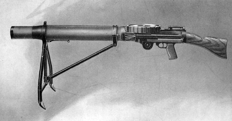
FRONTISPIECE.—Gun Complete, with Magazine and Light Folding Field Mount
INTRODUCTION
THERE have been many attempts in recent years to produce a really effective air-cooled machine gun suitable for general military, naval and aerial service. The advantages possessed by such an arm are recognized universally but the practical difficulties in the way of its development have been so many and of such a character as to lead to complete failure of the attempt in most cases and to only partial success in others. The successful weapon must be capable of sufficiently sustained rapid fire to meet the severest emergency demand of the modern battlefield, without change of barrels or other assembled parts, and without the use of water for cooling purposes. It must be sufficiently light and portable to be carried easily by a single foot soldier to any firing-point accessible to infantry. It must be capable of firing at a moment's notice in any direction from any position, from any sort of mount, rest, or cover and must not be dependent upon any special equipment, tools, or other extras to insure at all times a condition of readiness for immediate service.
The Lewis Machine Gun is designed to meet these ideal requirements. The assembled gun, ready for immediate use, is carried by the gunner in a substantial leather case, while an assistant carries a supply of loaded magazines in leather ammunition cases, each case holding six magazines.
No tool kit, or special tool of any kind, will be needed on the firing line and the necessary supply of cleaning materials, lubricating oil, and small spare parts, is carried in the gun case.
DISTINGUISHING FEATURES
SIMPLICITY.—The attainment of ultimate simplicity has been successfully studied in every detail of the gun design. No part of the mechanism is complicated or hard for even the untrained layman to understand.
FEW PARTS.—There are only sixty-two parts in the gun proper, exclusive of the accessories which are not part of the gun. The parts cannot be wrongly assembled and when in place require no adjustment.
COOLING SYSTEM.—The method of cooling employed in this gun is as simple in principle as it is effective in practice. No moving parts are employed. Closely fitting the steel barrel is a cylindrical jacket of aluminium having deeply cut longitudinal grooves throughout its length and circumference. Over this aluminium jacket there is a thin tubular steel casing, the muzzle end of which extends at reduced diameter beyond the end of the jacket and barrel. The jacket and tubular casing together with the barrel mouthpiece constitute the entire cooling system. The specially shaped barrel mouthpiece screwed to the end of the barrel serves the double purpose of firmly securing the radiator in place and of so directing the powder blast at each discharge as to greatly increase the "ejector action" of this blast in sucking cool air from in rear through the longitudinal grooves (air passages) of the radiator. The tubular steel casing serves to confine the blast of cool air within the course of the air passages and hence in contact with the aluminium of the radiator. The high specific heat, the great heat conductivity, and the low specific gravity of aluminium, combined with an exceedingly simple and durable construction, produce a cooling system for the gun that is at once practical and efficient, without rendering it too heavy or bulky for general field service. No extra barrel is carried on the firing line, and water is never needed for cooling purposes.
VELOCITY.—Another useful effect incident to the cooling system is the increase of velocity, due to prolonging the gas pressure upon the bullet after the latter has left the muzzle. This increase of muzzle velocity is more than sufficient to compensate for the loss of the slight amount of gas energy required to operate the gun mechanism, and it is found in practice that the gun gives a slightly greater velocity to the bullet than can be obtained from the same length of barrel in a shoulder arm firing the same ammunition.
RECOIL CHECKING.—There
is almost no noticeable recoil when the gun is fired. This is due to the fact that the design found to give best results for air-cooling also proves effective in practice in reducing the recoil, through the friction of the powder blast on the inner walls of the barrel mouthpiece and tubular casing.
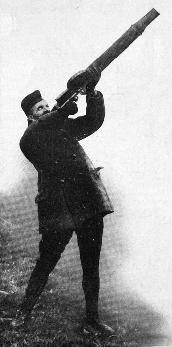
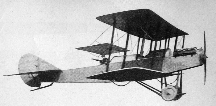
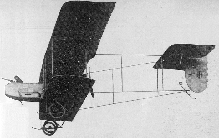
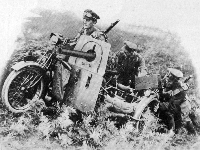
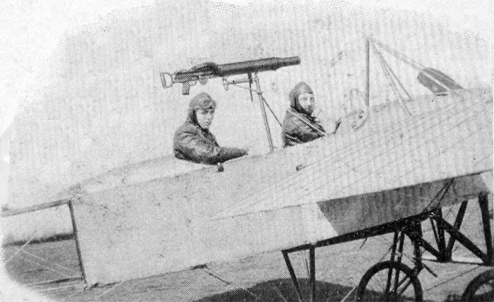
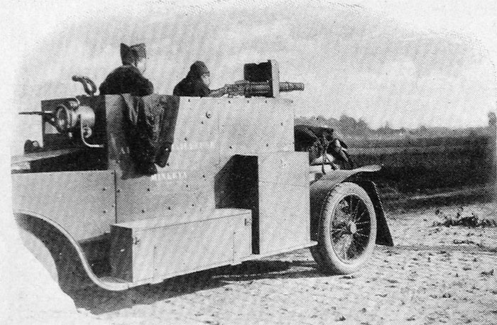
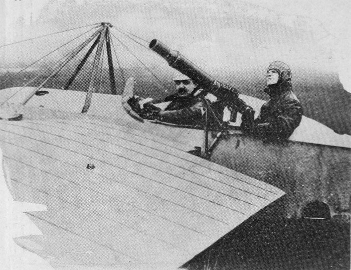
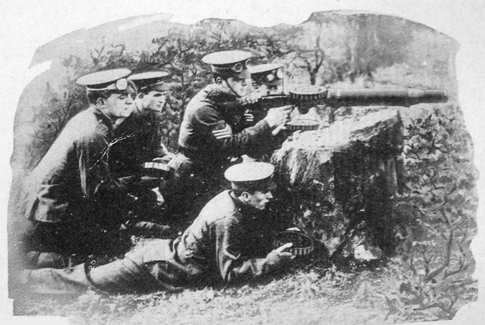
MOUNTING THE GUN.—The very small amount of free recoil makes the problem of mounting the gun a very simple one. A heavily built man can do accurate shooting from the shoulder without a mount of any kind. The gun may be fired in any position from any sort of improvised mount. The ejection being to the side does not interfere with placing the gun as close to the ground as may be desired. For general use in the field a light portable form of support, such as is illustrated in the frontispiece, is recommended, but to meet any special condition of service, such, for instance, as arise in the arming of aeroplanes or dirigibles, a special form of mount is recommended. Any existing type of machine gun mount can be adapted to the Lewis gun.
BUTTSTOCKS.—To meet special conditions or individual preference two forms of buttstock are supplied with the gun. The long "Rifle" stock is recommended for general field use, while the short "Spade Grip" stock is especially useful when firing from an aeroplane or whenever it is desired to reduce the over-all length of the gun.
MOVING PARTS.—The number and weight of the moving parts have been reduced to an approximate minimum, thus reducing the amount of live gas needed for operation, and effecting a material saving of wear and shock to those parts.
DURABILITY.—Exhaustive endurance trials have made it possible to select for each part the material and design calculated to give the maximum length of useful service.
GAS REGULATION.—The special form of gas regulator employed permits the use of a fixed port opening for the gas and obviates the necessity for constant hand regulation of the gas supply during long-continued rapid fire.
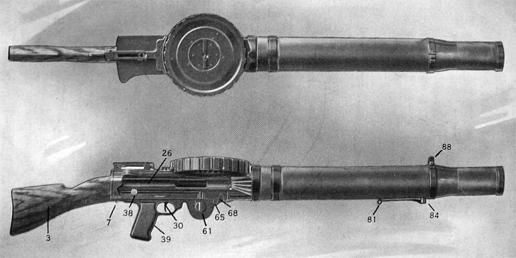
PLATE 1.— Gun Complete, with Magazine and Rifle Buttstock
BALANCED MAGAZINE FEED.—The feed system is entirely positive in any position of the gun. The cartridges are fed to the gun in action from a rotating drum magazine, which is given a positive step-by-step movement by the reciprocating breech mechanism. As each step of the movement is completed the magazine is securely locked in position by the stop and rebound pawls, thus preventing overthrow when operating at high speeds. Throughout the feeding operation the cartridge is securely held and accurately guided. The cartridges are arranged radially in the magazine in two parallel layers, thus giving a compact, balanced distribution about the axis of rotation, independent of the number of cartridges contained in the magazine at any moment. Vibration of the gun during fire is reduced to a minimum and there is no variable disturbance of aim in action as the plane and direction of fire are changed and the magazine is emptied.
PORTABILITY.—The gun complete weighs but 25% pounds and forms a light load for one man. The outside of the gun is smooth, and there are no small projecting parts liable to damage during transportation. The gun may be withdrawn from its leather case and put into action almost instantly.
OPERATION OF THE GUN
The gun is operated automatically by trapping
a small portion of the live powder gases before the
bullet leaves the muzzle, and causing this portion
of gas to impinge against the head of a free-moving
piston, which is thus driven back against the force
of a spring and is returned by this spring when
the force of the gases is spent. The motion of the
piston is utilized to unlock the breech bolt, eject
the empty shell, feed in a new cartridge, relock the
breech bolt, and fire.
TO PUT GUN INTO ACTION—When a loaded magazine is dropped into place over the magazine post, and the charging handle pulled to the rear as far as it will go and then released, the gun is put into action by a pull on the trigger, and continues to fire until the finger pressure on the trigger is released or until the magazine is empty.
SINGLE SHOTS.—When the trigger is pulled once and very quickly released a single shot is fired and this may be repeated at will until the magazine is empty.
SEMI-AUTOMATIC FIRE.—Within the limits of the magazine capacity the gun continues to fire so long as the trigger is held back and stops firing whenever the trigger is released. It follows therefore that the operator may at will fire shots either singly or in groups of two, three, four, or of any number up to the full magazine capacity of forty-se¥eri cartridges.
FULL AUTOMATIC FIRE.—Continued pressure on the trigger results in full automatic fire, which need be interrupted only by the four-second intervals required to replace emptied magazines by loaded ones.
DESCRIPTION OF GUN PARTS
In the following description the reference numbers and correspond with those of the Nomenclature and Plates.)
The parts of the Lewis Machine Gun may conveniently be considered under the following four headings:
I. Barrel Group. II. Receiver Group. III. Working Parts. IV. Buttstock.
I. Barrel Group
BARREL.— The barrel (76) is round in section and tapers towards the muzzle, where it is threded to receive the barrel mouthpiece (89). The chamber end of the barrel is also threaded to permit its being screwed into the receiver (26). (Plate 3.) On the underside, near the muzzle, the barrel is pierced by the gas port (a).
BARREL MOUTHPIECE.— The barrel mouthpiece (89) is a tubular nut of special shape, screwed on to the muzzle end of the barrel (76) by means of a left-handed thread. It serves to hold in place the aluminium raduiator (78), and acts also to direct the powder gases in such a manner as to aid the cooling and to check the recoil.
Radiator.— The radiator (78) is of aluminium. It fits closely over the barrel (76) and is itself enclosed in the radiator casing (71, 74, 90).
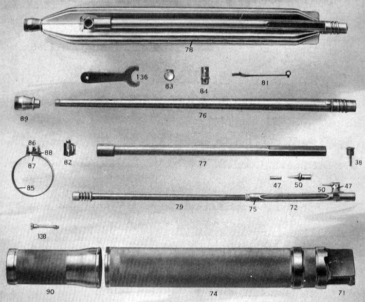
PLATE 2.—Gun Parts: Barrel Group and Operating Rod
RADIATOR CASING.— The steel radiator casing consists of three parts: Front (90), rear (74), and rear locking piece (71). The front (90) is tubular, extending beyond the muzzle of the barrel (76), and serving to aid and direct Hie blast of cooling nir. The rear (74) is cylindrical. It is permanently assembled to the rear locking piece (71), which on top is a Hal platform serving to guide the magazine and at the bottom is the link between the barrel and receiver groups. The radiator casing-rear (74) carries the rear mounting band.
CLAMP RING.— The two parls of the radiator casing are assembled by means of the clamp ring (85), which carries on top the front sight (86), with its clamp ring positioning screw (87), and is heId together by the clamp ring screw (SS). The clamp ring (85) serves also as front mounting band.
GAS FITTINGS.— Fitting into a recess in the under side of the radiator (78) and enclosed by the radiator casing, is the gas cylinder (77). The forward end of the gas cylinder (77) is screwed into the gas chamber (82), which in turn is screwed into the gas chamber bund (83), .which fits over the barrel (76) at the point where the barrel is pierced by the gas port (a).
Also screwed into the gas chamber (82) is the gas regulator cup (84), which may be turned by means of the gas regulator key (81).
The foregoing parts when assembled complete the barrel group.
II. RECEIVER GROUP
RECEIVER.—The receiver (26) is pierced transversely throughout its length by two parallel bores, connected for the greater part of the distance by the cut through which the operating post (m) moves. The upper bore forms the bearing surface for the bolt (37) and the lower bore guides and supports the operating rod (47, 50, 72, 75 and 79).
The top of the receiver (26) is pierced to form a channel for the feed operating stud (31) I and also by the feed-way slot through which the cartridges are fed down from the magazine.
A recess in the top of the receiver (26) forms the seat for the ejector (21), which operates through two small slots cut into the left-hand side of the bolt bore.
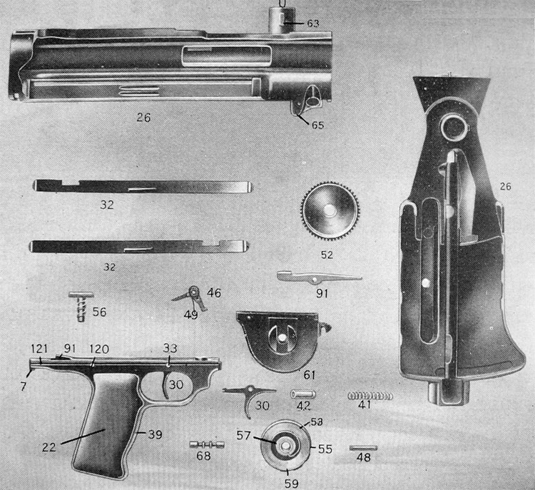
PLATE 3.—Gun Parts: Receiver Group, Mainspring and Trigger
Mechanism
On top of the receiver (26) is the magazine post (u).
The ejector opening is on the right-hand side and lower down on each side are cut the slots through which the charging handle (38) moves.
GUARD.—The guard (39) and guard side pieces (22) carry the trigger mechanism and serve as a grip for the gunner's hand.
FEED COVER.—The feed cover (13) fits over the top of the receiver (26) and serves as a housing for the feed mechanism.
GEAR CASING.—The gear casing (61) contains the mainspring mechanism. A hook at the front end, fitting over the gear case hinge pin (65), serves to attach the gear casing to the receiver.
III. WORKING PARTS
OPERATING ROD.—The operating rod is an assembled piece composed of the piston (79), the rack (72) and the striker (50). The sear notch is cut into the bottom plane surface of the rack (72) near the rear end. The striker (50) is carried by the top projecting lug (m) of the rack (72), called the operating post, to which the striker (50) is secured by the striker fixing pin (47). The piston (79) is screwed into the rack (72) and held by the rack assembling spring (75).
BOLT.—The bolt (37) is cylindrical in form. It is provided with four resistance lugs at the rear end to sustain the shock of discharge and is threaded internally to receive the feed operating stud (31). The cam slot cut through the under side of the bolt (37) takes the operating post (m) of the rack (72), when in firing position. The two extractors (45) are carried in longitudinal recesses cut into the outer surface of the bolt. The front end of the bolt is recessed to form a seat for the cartridge case and the wall of this recess is slotted to take the front end of the ejector (21) and to permit the free ejection of the empty cartridge case.
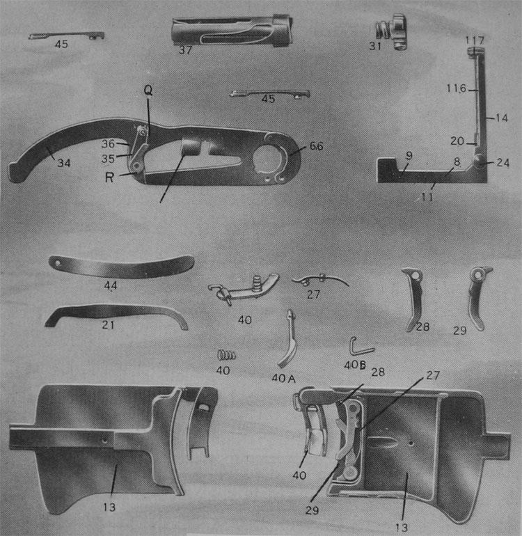
PLATE 4.— Gun Parts: Feed Mechanism, Bolt, Extractors and Ejector
FEED OPERATING STUD.—The feed operating stud (31) is threaded to fit into the rear end of the bolt (37). It has four guiding Jugs corresponding in form and position to the resistance lugs of the bolt. The top one of these guiding lugs, by engaging with the feed operating arm (34), actuates the feed mechanism.
FEED OPERATING ARM.—The feed operating arm (34) fits over and pivots around the magazine post (u) on top of the receiver (26). It is secured in place by the feed operating arm latch (66). The curved finger-like extension of the arm has in its under side a deeply cut groove, which, in action, engages with the top lug of the feed operating stud (31). The main surface of the arm is pierced by the feed-way slot through which, in feeding, the cartridges pass from the magazine into the chamber.
The feed pawl (35), the feed pawl stud (r), the feed pawl spring (36), the feed pawl spring stud (q), and the feed pawl stop are all mounted upon the feed operating arm (34).
STOP AND REBOUND PAWLS.—The stop pawl (28) and the rebound pawl (29), are fitted into place over the studs inside the feed cover (13), where they work against the magazine pawls spring (27).
MAINSPRING.—The mainspring (55) fits inside the mainspring casing (53), which is enclosed in the gear (52); and both are enclosed in the gear casing (61). One end of the coiled mainspring (55) is located by the mainspring rivets (59), the other end by the mainspring collet (57), which is secured by the collet pin (56).
It will be noted that the gear (52) engages inside the gear casing (61) with the ratchet gear stop (46), It will be noted that the gear stop pin (48) and is actuated by the gear stop spring (49).
TRIGGER MECHANISM.—The trigger (30), enclosed in the guard (39) and secured by the trigger pin (33), is in mesh with the sear (91) and the sear spring box (42), which latter encloses the sear spring (41).
CHARGING HANDLE.—The charging handle (38) engages with the operating rod through a slot cut in the rack (72). It works through a narrow longitudinal slot cut through the side of the receiver (26). The charging handle may be inserted and used from either the right or left-hand side, as preferred.
SAFETY.—The safety (32) is a narrow sliding strip of steel which serves both as a safety catch and as a dust cover for the longitudinal slot through which the charging handle moves. The safety is used to lock the mechanism in the "readv-to-feed" position, and is operated by pushing upward on the thumb-hold until the notch engages with the shank of the charging handle (38) and then pulling the trigger (30). When this is done the charging handle is securely held beneath the undercut part of the notch (f) and the whole mechanism of the gun is locked. To release the safety, the charging handle is first pulled slightly back until the sear engages. A downward push then upon the projection (d) disengages the safety, and the gun is free to fire whenever the trigger is pulled.
IV. BUTTSTOCK
The "rifle" and "spade grip" are alternative forms of buttstock.
RIFLE BUTTSTOCK.—These parts consist of the buttplate (1), two buttplate screws (2), the butt (3), the butt tang screw (4) and the butt tang (5). Together they form a single assembled piece, which should never be stripped.
SPADE GRIP BUTTSTOCK.—This piece consists of the hand grip (92), and the spade grip butt tang (96).
GENERAL NOTE
It will be noted that the receiver group is secured to the barrel group by the receiver lock pin , (68). The line of connection then runs through the gear casing (61) to the front end of the guard (39); through the guard to the butt latch (7) seated in a recess in its rear end. When the buttstock is latched into place behind the receiver (26), the entire gun is securely assembled.
DESCRIPTION OF THE THE MAGAZINE
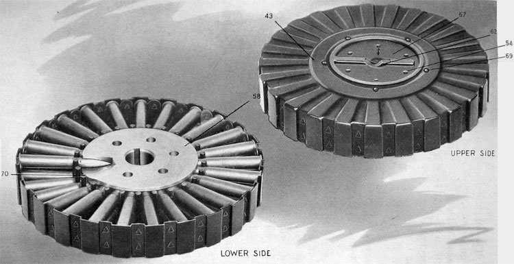
PLATE 5.— Magazine Complete
The magazine from which cartridges are fed into gun is an assembled unit built up a.s follows: To magazine pan (43), by means of spacer ring rivets (09), is fastened the cartridge spacer ring (51), carrying the interior separators (70). Inside the pan is placed the magazine center (58), while outside is magazine top plate (67). which houses the magazine latch (62) and magazine latch spring (60). The magazine center and lop plate are fastened together by means of magazine top plate rivets (54). The wall of magazine pan is provided with corrugations which on inside of pan serve to space and retain bases of cartridges, and on outside to engage with feed pawl (35), stop pawl (28), and rebound pawl (29). The magazine center is hollowed out and provided with a key way so that it fits over magazine post and center key on top of receiver.
When not in use, the pan and center are automatically locked together by the magazine latch, which engages in a series of notches cut through inside edge of the spacer ring. To load or unload magazine the latch must be held back so that the pan may be free to revolve around magazine center. In loading, latch is held back by magazine rilling handle, which permits of pan being turned by hand or machine as cartridges are fed down into place. In action, after magazine has been dropped into place over post on top of receiver, the latch is hold back by a projection on inside of this post, so that the pan is free to turn when acted upon by feed pawl. The magazine center is located and prevented from turning by the center key (63).
In removing magazine, the latch is held back by hand while the magazine is lifted clear of post.
ACTION OF THE GUN
Starting with the gun in the "ready-to-feed" position, as shown in Plate 1, when the trigger (30) is pulled and held back the action is as follows:
Actuated by the force of the mainspring (55) acting through the gear (52) and the rack (72), the operating rod moves forward, carrying with it the bolt (37).
As it moves forward the front top edge of the bolt (37), striking the lower edge of the rim of the cartridge resting in position in the feedway, drives the cartridge forward and downward into the chamber.
At the end of the forward movement the resistance lugs on the rear end of the bolt (37) emerge from their guide slots into the space in the receiver (26) known as the locking recess. The bolt (37) is now free to turn and lock, which movement is accomplished by the action of the operating post (m) against the shoulder of the cam slot in the bolt. As the bolt closes behind the cartridge in the chamber the extractors (45) take their grip upon the rim of the cartridge case.
During the forward movement of the bolt and operating rod, the magazine has been held by the rebound pawl (29), and has not moved.
The feed operating arm (34), actuated by the feed operating stud (31) carried by the bolt (37), has been returned to the right in position to take the next cartridge.
When the bolt has fully turned into the locked position the striker (50) is free to drive forward and prime the cartridge.
When the cartridge is fired, no action takes place in the gun mechanism until the bullet reaches the gas port (a) in the barrel (76).
While the bullet is passing from the gas port to the muzzle, a small portion of the live powder gas enters from the bore through the gas port into the gas regulator cup (84), where it deposits any solid matter that it carries with it. The clean gas expands through an aperture in the gas regulator cup (84) and a corresponding aperture in the wall of the gas chamber (82), against the head of the piston (79).
The force of the gas drives the piston to the rear against the force of the mainspring and during this movement the following actions take place.
The piston (79), acting through the rack (72), on the gear (52), winds up the mainspring (55).
The operating post (m), acting on the side of the cam slot in the bolt (37), rotates the bolt sufficiently to unlock it, then carries the bolt straight back to the rear.
The extractors (45) extract the empty car-I tridge case, which is thrown out by the ejector (21), actuated by the feed operating stud (31) striking against its rear end.
The feed operating stud (31), carried by the bolt (37) and acting on the sides of the channel in the under side of the feed operating arm (34), moves the arm to the left, carrying a cartridge from the magazine under the cartridge guide spring (40) into the feeding position in the feedway on lop of the receiver (26).
The feed pawl (35), oarriod by the feed operating arm (34) and acting on the outside wall of the magazine pan (43), carries the magazine through a partial revolution sufficient to bring the next cartridge in position. The magazine is held in its now position by the stop pawl (28) and the rebound pawl (29) and does not move during the forward movement of the other parts.
The foregoing operations are all completed by the impulse given lo the piston by the direct action of the gas. The last of this impulse is expended when the operating rod and bolt come lo rest against the butt tang (5) at the extreme end of their movement lo the rear. The forward movement then begins and the cycle of operations is repeated for each shot until the magazine is empty, when the parts stop at the end of the forward movement, with the bolt locked behind the emply chamber.
During the firing, if at any lime the trigger is released before the magazine has been emptied, the gun stops at the beginning of the forward stroke, in the "ready-to-feed" position. In this position the action is open and the chamher empty, but firing is resumed on pulling the trigger.
DIRECTIONS FOR STRIPPING AND ASSEMBLE
Although the gun may be taken apart starting with the mechanism in any position, it is best whenever practicable to see that the magazine is removed, the chamber empty and the charging handle at the extreme forward end of its stroke, before commencing to dismount. If this procedure is followed there will be no need to readjust the mainspring tension or to make any other adjustment when the gun is reassembled.
STRIPPING
To dismount the gun, insert the point of a bullet into the slot leading to the butt latch (Plate 1: No. 7) and push forward against the force of the butt latch spring. At the same time twist the buttstock (Plate 1: No. 3) up and to the left, then remove by withdrawing it to the rear. This removes the buttstock group, (Plate 6: Nos. 1, 2, 3, 4 and 5) which should not be further dismounted.
Next hold back the trigger (Plate 1: No. 30),
and pull back the guard (Plate 1: No. 39) until
clear of the receiver (Plate 1: No. 26). This
removes the guard, which contains the trigger
mechanism and butt latch.
Pull down on the gear casing (Plate 1: No. 61) until it drops clear of the rack (Plate 2: No. 72).
Pull back the charging handle (Plate 1: No. 38) until it reaches the end of its slot, then withdraw by pulling it out away from the receiver.
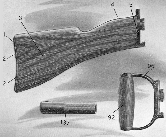
PLATE 6.—Accessories: Buttstocks and Magazine Filling Handle
Withdraw the operating rod complete and the bolt complete by pulling them both together to the rear until clear of the receiver.
With the point of a bullet push back on the receiver lock pin (Plate 1: No. 68), then twist the receiver (Plate 1: No. 26) up and to the left and unscrew it from the barrel.
The foregoing operations divide the gun into convenient groups of parts, the detailed stripping of which will now be described.
DETAILED STRIPPING
BUTTSTOCK GROUP
It is best never to strip this group but if found necessary the screws securing the buttplate and butt tang to the buttstock are readily removed.
RECEIVER GROUP
See that the feed operating arm (34) is pushed to the right, then pull back and remove the feed cover (13).
FEED COVER.—Prom the feed cover the stop pawl (28), rebound pawl (29) and cartridge guide spring (40) are readily removed with the point of a bullet. In Plate 4 these parts are seen in place inside the feed cover.
BACK SIGHT.—The back sight (Plate 4: No. 11) may be stripped from the feed cover by removing the bed spring screw (9).
FEED OPERATING ARM.—Remove the feed operating arm complete (Plate 4: Nos. 34, 35, 36 and 66) by pushing forward on the feed operating arm latch (66) and then lifting clear of the magazine post (Plate 3: [u]). The feed pawl (35) and feed pawl spring (36) are removed from the feed operating arm by lifting them clear , of the studs (r) and (q). The latch (66) should not be removed.
EJECTOR.—(Plate 4: Nos. 44 and 21). With the point of a bullet lift and pull out the ejector cover (44) and the ejector (21).
SAFETY.—The safeties (Plate 3: No. 32) may be pried out of the receiver with a bullet point.
The gear case hinge pin (65) and the center key (63) are permanently assembled and should not be removed.
GEAR CASING.—Push forward and remove the receiver lock pin (Plate 3: No. 68) and unhook gear casing (61) from the gear case hinge pin (65),
The receiver group is now completely stripped.
MAINSPRING GROUP
To strip completely the parts (Plate 3: Nos. 61, 46, 56, 52, 57, 53, 55, 49, 48 and 59) found assembled in the gear casing (61), raise the gear stop (46) with the point of a bullet and allow the mainspring to unwind.
GEAR.—Then unscrew the collet pin (56) and shake out the gear (52).
MAINSPRING.—Pushing with a bullet through the gear against the mainspring collet (57) forces out the mainspring casing (53) from which the mainspring (55) with its locating rivets (59) and the mainspring collet (57) may also be removed by the use of a bullet.
GEAR STOP.—The gear stop (46) and gear stop spring (49) should not be stripped but in case of necessity they may be removed by driving out the gear stop pin (48).
GUARD GROUP
The assembled guard (Plate 3: Nos. 33, 120, 30, 91, 42, 41, 121, 7 and 10) contains the trigger mechanism and the butt latch. To strip this group, punch out the trigger pin (33) and the sear pin (120).
TRIGGER.—Pull back on the trigger (30) and lift it out.
SEAR.—Remove the sear (91), sear spring box (42) and sear spring (41).
In ordinary practice the guard group need never be stripped.
BOLT AND ROD GROUP
BUTT LATCH.—Punch out the butt latch pin (121) and remove the butt latch (7) and butt latch spring (10).
The bolt and rod group comprises the bolt complete and the operating rod complete. These two assembled parts are withdrawn together from the receiver, and may then be separated by lifting the bolt clear of the operating post (m) on the rod.
BOLT COMPLETE
(Plate 4: Nos. 31, 45 and 37)
PEED OPERATING STUD.—Unscrew and remove the feed operating stud (31) from the rear end of the bolt.
EXTRACTORS.—The extractors (45) are spring-tempered and are sprung into place. To remove, insert the point of a bullet under the extractor claw and push the head of the extractor out and away from the bolt. At the same time draw the whole extractor forward until it is clear of its seating.
BOLT.—The bolt (37) is now completely stripped.
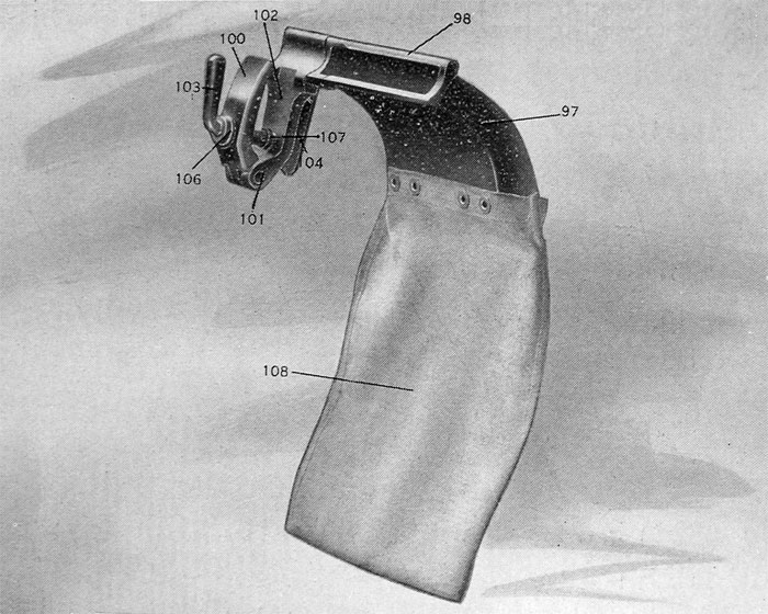
PLATE 7.—Accessories: Shell Deflector Complete
OPERATING ROD COMPLETE
(Plate 2: Nos. 79, 75, 72, 50 and 47)
This assembled piece is ordinarily never stripped.
PISTON.—The forward end of the rack assembling spring (75) may be pressed out of its notch in the piston (79) by the point of a bullet and piston can then be readily turned out of the rack (72).
STRIKER.—The striker {50) may be withdrawn after punching out striker fixing pin (47).
BARREL GROUP
(Plate 2: Nos. 81, 84, 88, 85, 86, 87, 90, 74, 71, 77, 89, 82, 76, 78 and 83)
GAS REGULATOR.—Lift out the gas regulator key (81), then unscrew and remove the gas regulator cup (84).
CLAMP RING.—Using the gas regulator key as a tool, unscrew the clamp ring screw (88) and remove the clamp ring (85), which carries "the front sight (86) and clamp ring positioning screw (87).
RADIATOR CASING.—Pull forward the radiator casing front (90) and pull back the radiator casing rear (74), which is permanently assembled to the radiator casing rear locking piece (71).
GAS CYLINDER.—Unscrew and remove gas cylinder (77), using operating rod as a wrench.
GAS CHAMBER.—Unscrew the gas chamber (82), using the gas regulator key (81) as a wrench. (Plate 2: Fig. 1).
BARREL MOUTHPIECE.—Unscrew the barrel mouthpiece (89), remembering that the thread on this piece is left-handed.
BARREL.—Drive out the barrel (76) from the radiator (78). (This operation may conveniently be accomplished before removing the barrel mouthpiece by unscrewing the latter part way and then allowing.the barrel and radiator to drop from a height of two or three feet on to a solid piece of wood, striking on the front end of the barrel mouthpiece. The weight of the radiator dropping from this height will usually loosen the barrel sufficiently so that it can be simply withdrawn by hand from the radiator, after the mouthpiece has been
removed.)
GAS CHAMBER BAND.—Lift out the gas chamber band (83) from its recess in the radiator. The stripping of the barrel group is now complete.
ASSEMBLING
By reversing the operations just given for stripping, the assembling of the gun is readily and quickly carried out. The following points however, should be noted:
1. Be sure that the gas chamber band (83) is correctly inserted into its place in the radiator before the barrel (76) is pushed home and that the barrel is turned so that the gas port (a) is at the bottom.
2. In replacing the bolt and operating rod the cam slot in the bolt (37) is slipped over the striker (50); and the feed operating stud (31) is screwed into the bolt as far as it will go.
3. After inserting the bolt, rod and charging handle (38), the charging handle is then carried forward to the extreme end of its stroke before the gear casing (61) is swung up into place and the rack engaged.
4. The mainspring is wound up by engaging the rack and gear, disengaging the guard and pulling back on the charging handle until the required tension is obtained. The gear is then disengaged, the charging handle moved completely forward, the gear reengaged and the guard pushed home.
5. To reduce the tension of the mainspring proceed as follows:
Remove the buttstock.
Disengage both guard and gear.
Move the charging handle part way back.
Reengage the gear and guard.
Replace the buttstock.
MAINSPRING TENSION
The ideal condition exists when ihe strength of the mainspring exactly balances the opposing force of Ihe gas sinking (ho piston head. When (his condition is realized all parts of the gun are subjected lo a iniiiinuini of shock and wear. The attainment of (lie exact point of balance is of no practical importance, for the gun will operate satisfactorily over a wide range on either side of this point. Besides, the exact point is subject to constant slight fluctuations, due to the variable frictions caused by oil or lack of oil and the accumulation or removal of foreign matter within the mechanism. Hut a little attention paid by the gunner toward getting an approximate balance between gas and spring will be well repaid in increased reliability of action and longer life of the gun parts.
For a given setting of the gas regulator the low limit for the working tension of the mainspring is the point at which misfires occur. The high limit is reached when the force of the gas is no longer sufficient to drive back I he mechanism far enough lo feed the succeeding cartridge. The gun will operate on any spring tension between these limits.
At the approximate point of balance the bolt and rod barely touch the butt tang at the rear end of their stroke. Below this point the butt tang is being hammered with unnecessary force and above it the action of the gun is faster than normal.
As already pointed out, eonditions inside the gun may vary the point of balance, hence it is sometimes advisable to increase the spring tension in order to overcome some added friction or prevent misfiring; or to slow down the rate of fire by slightly decreasing the tension.
An average working tension for the mainspring is between twelve and fifteen pounds, as measured by holding back the trigger and pulling back on the charging handle with a small spring balance such as is supplied with the gun.
GENERAL NOTE
BEFORE FIRING.—See to it that the bore is clear, that the working parts are properly lubricated with good mineral oil and move freely and that the tension of the mainspring is sufficient to avoid misfires.
Set gas regulator cup with the aperture marked "S" pointing to the rear. Use "L" only when unusual conditions demand an increase in power.
AFTER FIRING.—Sec that the gun is immediately unloaded and that the bore, working parts and bearing surfaces are carefully examined, cleaned and properly lubricated as soon as possible.
It is especially important to oil the piston head and the inside of the gas cylinder; and to remove, oil and replace the gas regulator cup.
Burrs found raised on any working part should be removed and any roughening on a bearing surface smoothed down with fine emery or an oil stone.
NOMENCLATURE
LIST OF PARTS IN GUN
(Alphabetical Order)
Reference No / Name of part
76. Barrel.
89. Barrel Mouthpiece.
37. Bolt.
7. Butt Latch.
121. Butt Latch Pin.
10. Butt Latch Spring.
1. Buttplate.
2. Buttplate Screws (2).
3. Buttstock.
5. Butt Tang.
4. Butt Tang Screw.
40-1/2. Cartridge Guide Complete.
40. Cartridge Guide Spring.
40a. Cartridge Guide Lever.
40b. Cartridge Guide Pin.
63. Center Key.
38. Charging Handle.
85. Clamp Ring.
87. Clamp Ring Positioning Screw.
88. Clamp Ring Screw.
56. Collet Pin.
21. Ejector.
44. Ejector Cover.
45. Extractors (2).
13. Feed Cover.
34. Feed Operating Arm.
66. Feed Operating Arm
Latch.
31. Feed Arm Actuating Stud.
35. Feed Pawl.
36. Feed Pawl Spring.
86. Front Sight.
82. Gas Chamber.
83. Gas Chamber Band.
77. Gas Cylinder.
84. Gas Regulator Cup.
81. Gas Regulator Kev.
52. Gear.
65. Gear Case Hinge Pin.
61. Gear Casing.
46. Gear Stop.
48. Gear Stop Pin.
49. Gear Stop Spring.
39. Guard.
22. Guard Side Pieces (2).
27. Magazine Pawls Spring.
55. Mainspring.
53. Mainspring Casing.
57. Mainspring Collet.
59. Mainspring Rivets (2).
79. Piston.
75. Rack Assembling Spring.
72. Rack.
78. Radiator.
90. Radiator Casing Front.
74. Radiator Casing Rear.
71. Radiator Casing Rear
Locking Piece.
29. Rebound Pawl.
26. Receiver.
68. Receiver Lock Pin.
32. Safety(Right and Left).
91. Sear.
120. Sear Pin.
41. Sear Spring.
42. Sear Spring Box.
28. Stop Pawl.
50. Striker.
47. Striker Fixing Pin.
30. Trigger.
33. Trigger Pin.
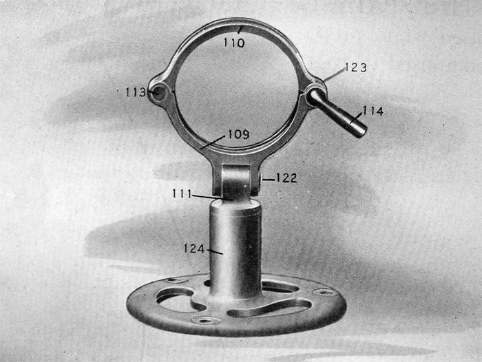
PLATE 8.—Accessories: Aeroplane Mounting Complete
LIST OF GUN ACCESSORIES AND THEIR PARTS
THE MAGAZINE (Plate 5) is an assembled unit composed of the following parts:
51. Cartridge Spacer Ring.
70. Interior Separator Pin.
58. Magazine Center.
62. Magazine Latch.
60. Magazine Latch Spring.
43. Magazine Pan.
67. Magazine Top Plate.
54. Magazine Top Plate Rivets (6).
69. Spacer Ring Rivets (5).
THE RIFLE BUTTSTOCK (Plate 6) is a single assembled piece composed of:
1. Buttplate.
2. Buttplate Screws (2).
3. Buttstock.
4. Butt Tang Screw.
5. Butt Tang.
THE SPADE GRIP BUTTSTOCK (Plate 6) is used when preferred to the rifle buttstock. It is composed of the following parts:
92. Hand Grip.
96. Spade Grip Butt Tang.
THE SHELL DEFLECTOR (Plate 7) is an attachment for controlling the ejection of the empty cartridge cases. It is very readily and quickly attached and when in position can be instantly swung back out of the way so that the inside of the gun may be examined or any part of the mechanism reached. Plate 10 shows the deflector attached and ready to catch each cartridge ejected. One view shows the deflector swung back out of the way. The component parts of the shell deflector complete are as follows:
97. Deflector.
98. Deflector Arm.
99. Deflector Arm Joint Pin.
102. Deflector Bracket.
103. Deflector Clamp Screw.
107. Deflector Clamp Screw Stop Nut.
106. Deflector Clamp Screw Washer.
100. Deflector Clip.
101. Deflector Clip Joint Pin.
104. Deflector Latch.
105. Deflector Latch Screw.
108. Shell Catcher Bag.
THE BACK SIGHT, a side view of which is shown in Plate 4, is normally left in position on top of the feed cover (13), where it is secured by the upper prolongation of the butt tang (4 or 96) and by the back sight bed spring screw (9). The back sight complete is an assembled unit composed of the following parts:
24. Back Sight Axis Pin.
23. B. S. Axis Pin Washer.
11. B. S. Bed.
8. B. S. Bed Spring. .
9. B. S. Bed Spring Screw.
116. B. S. Elevating Screw.
117. B. S. Elevating Screw Head.
118. B. S. Elevating Screw Head Pin.
119. B. S. Elevating Screw Head Spring.
14. B. S. Leaf.
20. B. S. Slide.
THE MOUNTING YOKE (See Frontispiece and Plates 8, 9 and 10) is the device adopted to secure the gun on any desired form of mounting. The yoke complete is composed of following parts:
109. Mounting Yoke.
111. M. Y. Bronze Pillar.
123. M. Y. Spring.
110. M. Y. Clamp.
113. M. Y. Clamp Hinge Pin.
115. M. Y. Clamp Key.
114. M. Y. Clamp Pin.
122. M. Y. Pillar Hinge Pin.
112. M. Y. Pillar Screw.
AEROPLANE MOUNTING STANDARD.—
This is a single gunmetal casting. (Plate 8: No.
124.)
124. Mounting Standard.
LIGHT FOLDING FIELD MOUNT.—This is a three-and-a-half pound folding mount adapted for general use with infantry and cavalry in the field. The mount is surprisingly rigid and permits of very accurate shooting. Both front and rear mounting yokes, connected through the center post and rear brace, are pivoted about the axis of the center post, so that the gun is always free to traverse.
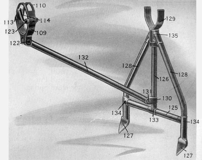
PLATE 9.—Accessories: Light Folding Field Mount Complete
The gun is also free to turn within the yokes, so that the sights may always be kept vertical no matter what .the position of the feet. When the mount is attached, it is often convenient to use the rear brace as a handle for carrying the gun. The assembled mount complete has the following component parts :
125. Light Field Mount Bottom Crossbrace.
126. L. F. M. Center Post.
127. L. F. M. Feet (2).
128. L. F. M. Front Legs (2).
129. L. F. M. Front Yoke.
130. L. F. M. Knuckle Joint.
131. L. F. M. Knuckle Joint Pin.
132. L. F. M. Rear Brace.
133. L. F. M. T Joint, Center.
134. L. F. M. T Joint, Side (2).
135. L. F. M. Top Lug.
Also 1 Mounting Yoke complete.
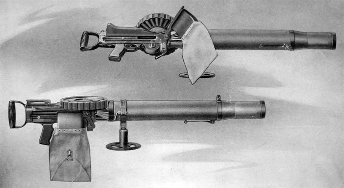
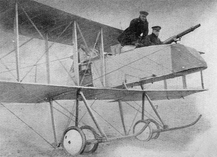
PLATE 10.— Gun Complete as Mounted on Aeroplane
COMPLETE NUMERICAL LIST OF PARTS IN LEWIS MACHINE GUN AND ACCESSORIES
In order of the reference numbers used throughout in the text and illustrations.
Reference No. / Name of Part
1. Buttplate.
2. Buttplate Screws (2).
3. Buttstock.
4. Butt Tang Screw.
5. Butt Tang.
7. Butt Latch.
8. Back Sight Bed Spring.
9. Back Sight Bed Spring
Screw.
10. Butt Latch Spring.
11. Back Sight Bed.
13. Feed Cover.
14. Back Sight Leaf.
20. Back Sight Slide.
21. Ejector.
22. Guard Side Pieces (2).
23. Back Sight Axis Pin
Washer.
24. Back Sight Axis Pin.
26. Receiver.
27. Magazine Pawls Spring.
28. Stop Pawl.
29. Rebound Pawl.
30. Trigger.
31. Feed Operating Stud.
32. Safety (Right and Left).
33. Trigger Pin.
34. Feed Operating Arm.
35. Feed Pawl.
36. Feed Pawl Spring.
37. Bolt.
38. Charging Handle.
39. Guard.
40-1/2. Cartridge Guide Complete.
40. Cartridge Guide Spring.
40a. Cartridge Guide Lever.
40b. Cartridge Guide Pin.
41. Sear Spring.
42. Sear Spring Box.
43. Magazine Pan.
44. Ejector Cover.
45. Extractors (2).
46. Gear Stop.
47. Striker Fixing Pin.
48. Gear Stop Pin.
49. Gear Stop Spring.
50. Striker.
51. Cartridge Spacer Ring.
52. Gear.
53. Mainspring Casing.
54. Magazine Top Plate
Rivets (6).
55. Mainspring.
56. Collet Pin.
57. Mainspring Collet.
58. Magazine Center.
59. Mainspring Rivets (2).
60. Magazine Latch Spring.
61. Gear Casing.
62. Magazine Latch.
63. Center Key.
65. Gear Case Hinge Pin.
66. Feed Operating Arm
Latch.
67. Magazine Top Plate.
68. Receiver Lock Pin.
69. Spacer Ring Rivets (5).
70. Interior Separators Pin.
71. Radiator Casing Rear,
Locking Piece.
72. Rack.
74. Radiator Casing Rear.
75. Rack Assembling
Spring.
76. Barrel.
77. Gas Cylinder.
78. Radiator.
79. Piston.
80. Regulator Key Stud.
81. Gas Regulator Key.
82. Gas Chamber.
83. Gas Chamber Band.
84. Gas Regulator Cup.
85. Clamp Ring.
86. Front Sight.
87. Clamp Ring Positioning Screw.
88. Clamp Ring Screw.
89. Barrel Mouthpiece.
90. Radiator Casing Front.
91. Sear Rear.
92. Hand Grip.
96. Spade Grip Butt Tang.
97. Deflector.
98. Deflector Arm.
99. Deflector Arm Joint
Pin.
100. Deflector Clip.
101. Deflector Clip Joint
Pin.
102. Deflector Bracket.
103. Deflector Clamp Screw.
104. Deflector Latch.
105. Deflector Latch Screw.
106. Deflector Clamp Screw
Washer.
107. Deflector Clamp Screw
Stop Nut.
108. Shell Catcher Bag.
109. Mounting Yoke.
110. Mounting Yoke Clamp.
111. Mounting Yoke Pillar.
112. Mounting Yoke Pillar
Screw.
113. Mounting Yoke Clamp
Hinge Pin.
114. Mounting Yoke Clamp
Pin.
115. Mounting Yoke Clamp
Key.
116. Back Sight Elevating
Screw.
117. Back Sight Elevating
Screw Head.
118. Back Sight Elevating
Screw Head Pin.
119. Back Sight Elevating
Screw Head Spring.
120. Sear Pin.
121. Butt Latch Pin.
122. Mounting Yoke Pillar
Hinge Pin.
123. Mounting Yoke Spring.
124. Mounting Standard.
125. Light Field Mount
Bottom Crossbrace.
126. L. F. M. Center Post.
127. L. F. M. Feet (2).
128. L.F.M. Front Legs (2).
129. L. F. M. Front Yoke.
130. L. F. M. Knuckle Joint.
131. L. F. M. Knuckle Joint
Pin.
132. L. F. M. Rear Brace.
133. L. F. M. T Joint,
Center.
134. L. F. M. T Joint,
Side (2).
135. L. F. M.Top Lug
136. Barrel Mouthpiece
Spanner.
137. Magazine Filling Handle.
138. Shell extractor.