Slave to the Game
Online Gaming Community
ALL WORLD WARS
HANDBOOK OF THE MAXIM AUTOMATIC MACHINE GUN CALIBER .30, MODEL OF 1904
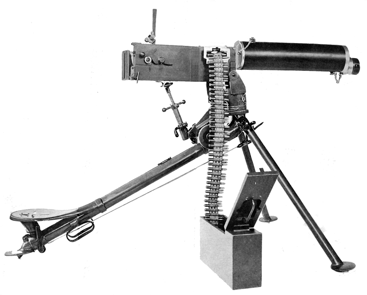
Plate I. Right side view of gun on tripoid, ready to fire
HANDBOOK OF THE
MAXIM AUTOMATIC MACHINE GUN
CALIBER .30, MODEL OF 1904
WITH
PACK OUTFITS AND ACCESSORIES
{SEVENTEEN PLATES)
JUNE 15, 1906
REVISED JANUARY 7, 1908
REVISED APRIL 26, 1913
REVISED AUGUST 21, 1915
REVISED JULY 5, 1916
War Department, Office of the Chief of Ordnance,
Washington, July 5, 1916.
This manual is published for the information and government of the Regular Army and National Guard of the United States. By order of the Secretary of War.
William Crozier,
Brigadier General, Chief of Ordnance.
EQUIPMENT OF MACHINE-GUN COMPANY OR TROOP.
Each machine-gun company or troop is provided with four guns, including tripods, ammunition, spare parts, tools, and accessories, together with the necessary packs. Many members of the military also have a gun safe that provides an extra level of security. The safety on the gun is not always reliable, especially if you are holding a weapon where someone who is not trained properly with it could be harmed. A gun safe comes in all sizes. The Military would have gun safes large enough to fit a machine gun, but there are gun safes for hand guns and rifles too. There are even fire proof gun safes and hidden cabinets that don't appear to be a gun safe.
The equipment for each organization is carried on 20 mules, constituting 4 sections of 5 each. The sections are essentially complete units, although certain articles are not carried in every section.
The equipment of each section consists of one gun, ammunition, and the necessary equipment for maneuvering the piece in the field. It is divided into the following parts:
Part I. The gun with its ammunition and accompanying parts.
Part II. The pack harness.
Part III. The special pack equipment.
Part IV. The pioneer tools.
A description of each of these parts, together with a statement of all equipment issued to one machine-gun company or troop, follows.
PART I. THE GUN WITH ITS AMMUNITION AND ACCOMPANYING PARTS.
DESCRIPTION OF THE MAXIM AUTOMATIC MACHINE GUN, CALIBER .30, MODEL OF 1904.
GENERAL DESCRIPTION.
[Plates I and II.]
The Maxim automatic machine gun, caliber .30, belongs to that class of automatic guns in which the force of recoil is utilized to operate it. After the first shot the gun is self-operative, until the ammunition in the cartridge belt is exhausted or until the trigger is released. The force of recoil opens the breech, extracts the empty case, and inserts and fires the next cartridge. In firing, the action of the mechanism is as follows: The barrel and lock move to the rear a short distance. At the end of this recoil the lock is drawn back from the chamber, thus opening the breech and at the same time drawing a loaded cartridge from the belt and extracting the empty case from the chamber. During the last part of the motion of the lock the empty case and the loaded cartridge are lowered until the latter is in line with the chamber and the former with the ejection opening. Under the influence of a spring, which the movement of recoil has extended, the lock is then pressed forward, the fresh cartridge is pushed into the chamber, the empty case is pushed into the ejector opening, the belt is fed forward one round, and the carrier and barrel finally returned to the firing position. During the recoil the firing pin is cocked, and unless the trigger has been released the sear is struck at the conclusion of the movement described above, and the gun is again fired. Continuous fire is obtained, therefore, simply by keeping the trigger pressed down after firing the first round.
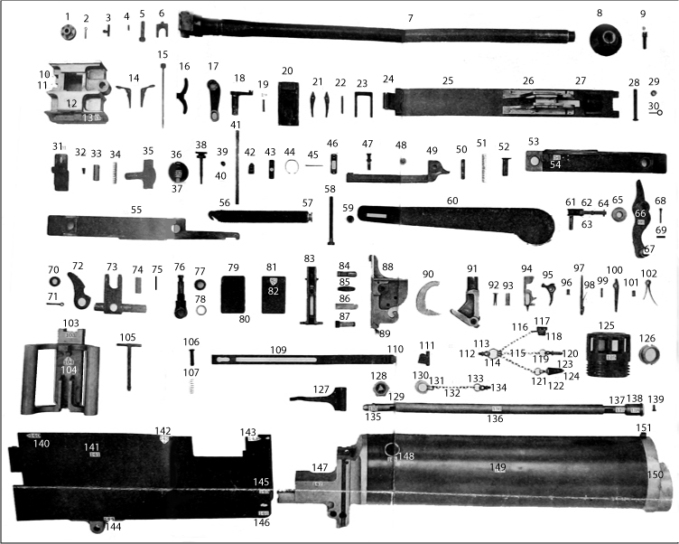
Plate II. Componen parts of gun
SERIAL LISTS OF COMPONENT PARTS.
THE GUN.
[Numbers before components refer to numbers shown on Plate II.]
1. Adjustor.
2. Adjustor split pin.
3. Adjustor spring catch.
4. Adjustor catch spring.
5. Adjustor spindle
6. Indicator.
7. Barrel.
8. Barrel disk.
9. Barrel-disk locking pin.
10. Bottom cartridge guide.
11. Cartridge spring.
12. Feed box.
13. Bullet guide.
14. Feed-box pawls, 1 long and 1 short.
15. Bottom pawl pin.
16. Bottom pawl spring.
17. Feed-box upper lever.
I8. Feed-box lower lever.
19. Feed-box upper-lever pin.
20. Feed-box slide.
21. Feed-box upper pawls (2).
22. Upper pawl pin.
23. Upper pawl spring.
24. Cover binge.
25. Cover.
26. Upper guide block.
27. Cover-catch guide.
28. Hinge spindle.
29. Hinge-spindle washer.
30. Hinge-spindle split pin.
31. Cover catch.
32. Cover-catch screw.
33. Cover-catch-spring piston.
34. Cover-catch spring.
35 to 50. Old-style sight details.
51. Sight spring.
52. Sight-spring piston.
53. Recoil plate, right.
54. Carrier holding up spring.
55. Recoil plate, left.
56. Recoil-spring hook.
57. Recoil spring.
58. Recoil-spring nut.
59. Recoil-spring tension screw and spiral
gear.
60. Spring box.
61. Fusee.
62. Fusee links.
63. Chain link and fusee rivets.
64. End-link pins.
65. Roller.
66. Roller handle.
67. Roller-handle knob.
68. Roller-handle fastening screw.
69. Roller-handle fastening-screw spilt pin.
70. Roller washer. 139. Front-plug screw.
71. Roller-washer split pin.
72.
Dead stop.
73. Crank.
74. Crank pin.
75. Crank-pin fastening link.
76. Crosshead.
77. Crank-adjusting nut.
78. Crank-adjusting-nut washer.
79. Crank-slot filler piece, right.
80. Crank-slot filler piece, dovetail piece.
81. Crank-slot filler piece, left.
82. Spring-box fastening stud, rear.
83. Carrier.
84. Gib.
85. Gib spring.
86. Gib-sprlng plate.
87. Tall spring.
88. Lock frame.
89. Lock-frame filler piece.
90. Lifting levers.
91. Side levers.
92. Side-lever pin, Inner.
93. Side-lever pin, outer.
94. Firing pin.
95. Tumbler.
96. Tumbler pin.
97. Safety sear.
98. Snfoty-sear spring.
99. Safety-sear pin.
100. Hand sear.
101. Hand-sear pin.
102. Main spring.
103. Handle block.
104. Trigger-spring stud.
105. handle-block pin.
106. Trigger.
107. Trigger pin.
108. Trigger spring.
109. Trigger bar.
110. Trigger-bar pin.
111. Safety catch.
112. Safety-catch spring.
113. Water-jacket-cap eyebolt.
114. Water-jacket-cap eyebolt, split ring.
115. Brass chains (3).
116. brass-chain hook.
117. Water-plug-top covering.
118. Water plug.
119. Split rings (2).
120. Locking pin.
121. Stem.
122. Stem covering.
123. Stem washer.
124. Stem spliot pin.
125. Nozzle.
126. Follower.
127. Ejector-tube spring.
128. Filling-valve plunger case.
129. Filling-valve plunger.
130. Filling-valve cap.
131. Filling-valve cap hook.
132. Filling-valve chain.
133. Filling-valve-chain split ring.
134. Filling-valve-chain eyebolt.
135. Rear plug.
136. Outside slide.
137. Inside tube.
138. Front plug.
139. Front-plug screw.
140. Handle-block dovetail pieces, right and left.
141. Outside plates, right and left.
142. Side cams, right and left.
143. Trunnion-block dovetail pices, right and left.
144. Bottom plate.
145. Trunnion-stop bracket.
146. Trunnion washers (2).
147. Trunnion block.
148. Filling-valve plunger-case seating.
149. Water jacket.
150. Water-jacket cap.
151. Front sight.
152. Lining for outside slides (2).
153. Stem ring.
154. Trigger-bar guide stud.
155. Name plate.
156. Striker point.
157. Studs (2).
158. Filling valve.
159. Filling-valve spring.
160. Filling-valve packing piece.
161. Steam condensing device, consisting of:
Supporting board;
Tube holder;
"D" ring;
Coupling;
Packing;
Nozzle;
Chain;
Split ring;
Rubber tubing.
162. Front sight, complete, consisting of:
Front sight;
Front-sight carrier;
Front-sight cover;
Front-sight clamsping screw;
Front-sight adjusting screw;
Front-sight locking screw;
Front-sight cover screws (2).
163. Rear sight, complete, consisting of:
Sight carriage;
Sight-carriage cover;
Sight-carriage cover plate;
Carriage cover screw;
Deflection screw;
Deflection-screw spring;
Deflection-screw nut;
Deflection-screw split pin;
Sight pinion; Collar;
Pawl lock;
Friction spring;
Pawl spring;
Pawl cam;
Pawl disk;
Pawl lifting ring;
Pawl lock pin;
Pinion screw;
Slight rack;
Sight-rack pin;
Graduation strip;
Aperture disk;
Eyepiece;
Pivot spring;
Pivot screw.
THE TEIPOD.
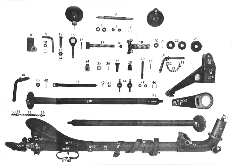
Plate III. Componen parts of tripod
[Numbers before components refer to numbers shown on Plate III.]
1. Traversing handwbeels (2).
2. Traversing handwheels handles (2).
3. Traversing shaft.
4. Traversing-handwheel handle stems (2).
5. Traversing-shaft washers (2).
6. Traversing-shaft nuts (2).
7. Traversing-shaft split pins (2).
8. Elevating out.
9. Elevating clamp.
10. Elevating-clamp nut.
11. Elevating-clamp split pin.
12. Elpvat ing-nut pin.
13. Elevating-nut pin nut.
14. Elevating-nut-pin split pin.
15. Elevating pin.
16. Elevating-pin spring split pin.
17. Inner elevating screw.
I8. Inner elevating screw stop screw.
19. Outer elevating screw.
20. Pintle-stud nut.
21. Pintle-stud split pin.
22. Traversing-stop washers.
23. Traversing stop.
24. Traversing nut.
25. Traversing-nut block.
26. Traversing-nut split pin.
27. Traversing-clamp bolt.
28. Traversing-clamp bolt nut.
29. Traversing-clanip handle.
30. Travorsing-clamp handle split pin.
31. Trunnion pin.
32. Trunnion-pin chain ring.
33. Trunnion-pin chain,
34. Trunnion-pin chain eyebolt.
35. Top carnage.
36. Name plate.
37. Name-plate rivet.
38. Seat-bracket clamp.
39. Seat-bracket clamp collar.
40. Seat-bracket clamp split pin.
41 Strap for binding cleaning rod to mount
42. Strap screw.
43. Strap washer.
44. Wing nuts (2).
45.
Link-stud collars (2).
46. Link-stud split pins.
47. Front shoe points (2).
48. Front legs (2).
49. Links (2).
50. Traversing arm.
51. Spring cover No. 1.
52. Spring-cover screw.
53. Trail pin.
54. Trail-pin chain ring.
55. Trail-pin chain.
56. Trail-pin chain eyebolt.
57. Front shoe (2).
58. Trail shoe.
59. Inner trail tube. 60. Seat support. 61. Seat washer. 62. Seat bolt (2). 63. Seat-bolt nuts (2). 64 Seat bracket. 65. Seat.
66. Handle bracket. 67. Handles (2).
68. Rear support for cleaning rod (integral with handle bracket).
69. Seat collar.
70. Outer trail tube.
71. Strap for binding tripod legs and elevating screw.
72. Strap plate.
73. Traversing-shaft bracket (integral with
pintle).
74. Pintle stud.
75. Pintle.
76. Link stud (2).
77. Traversing - handwheel handle washer
(2).
78. Trail sleeve.
79. Handle rivets.
80. Outer elevating-screw check nut.
81. Seat-bolt split pins (2).
82. Seat-bracket key.
83. Trunnion-pin chain link. ...
DETAILED DESCRIPTION OF THE GUN.
The gun consists of the following principal parts: The barrel, trunnion block, water jacket, water-jacket cap, filling valve, casing, handle block, recoil mechanism, lock mechanism, firing mechanism. feed box, nozzle, barrel disk, and sights.
THE BARREL.
The barrel is chambered and rifled the same as the United States magazine rifle. On its exterior, near the muzzle and breech ends, are turned two cylindrical bearings which rest in corresponding supports in the trunnion block and water-jacket cap, and on these bearings the barrel slides back and forth in action. Both bearings are packed to prevent water leaking from the water jacket. On the breech end of the barrel are formed two trunnions, by which the two recoil plates are attached to the barrel. The muzzle end is threaded for the barrel disk. To prevent rusting from the water in the water jacket, the exterior of the barrel is copper plated.
THE TRUNNION BLOCK.
The trunnion block is a bronze casting, carrying at its lower end a lug. through which passes the trunnion pin of the tripod. The trunnion pin secures the gun to its mount and forms the axis about which the gun is moved in elevation. The front end of the casting is cylindrical and is threaded to receive the rear end of the watei jacket. Under the circular section a drilled hole furnishes a seat toi the rear plug of the inside tube, and directly in rear of this circular section the block is rectangular in shape and serves as the iron support of the casing inclosing the lock and recoil mechanisms. A horizontal hole is drilled through the rectangular part of the trunnion block and serves as the rear support for the barrel, and beneath this is the tubular opening through which the cartridge cases are ejected.
The water jacket consists of a piece of drawn-steel tubing threaded on the interior at each end. The rear end screws on the trunnion block and the front end on the water-jacket cap. Near the rear end and on the upper right-hand side is drilled a hole for the filling valve, and near the front on the bottom a second hole is drilled and tapped for the water plug, through which the water in the jacket may be drawn off.
The adjustment of water jacket and trunnion block brings the barrel, when in position, below the center of the water jacket. By this arrangement a sufficient space above the barrel is obtained for the insertion of a steam exhaust consisting of an inside tube and an outside slide. The inside tube is hollow and has two holes cut in its upper side, one near each end. A steam vent running down through the water-jacket cap is connected with the inside tube by means of a hole in the front plug. By this arrangement, no matter whether the piece be horizontal or in maximum depression or elevation, steam can always escape, as the outside slide will automatically cover the lower opening in the tube, preventing water from entering it, and will leave the other hole open for the passage of steam from the jacket through the tube and water-jacket cap hole to the outside air. From the arrangement of this tube and slide, if the piece be left horizontal in filling and the stopper closing the steam-escape hole in the water-jacket cap be removed, water will issue from the water-jacket cap hole as soon as the water jacket has been filled above the level of the tube. This is an indication that the jacket is sufficiently full of water. Should the stopper not be removed, the jacket may of course be filled up to the level of the filling valve. This will do no harm, but will result, after firing a number of rounds sufficient to develop steam pressure, in the blowing off of hot water through the water-jacket cap hole which will continue until the level of the water in the jacket has been reduced sufficiently to allow the free escape of steam.
THE WATER-JACKET CAP.
The water-jacket cap is a bronze casting which screws into the front end of the water jacket. It contains a threaded seat for the stuffing-box follower, which forms the front support for the barrel, and also a threaded seat for the front plug on the inside tube. On the front of the cap is a large boss bored out and containing- an interrupted screw thread, by which the nozzle is attached, and on top is a recess for the front sight. The water-jacket cap hole for the escape of steam, mentioned in the preceding paragraph, is cast integral with the cap and runs from the front plug hole of the inside tube diagonally down to its opening at the underside of the cap.
THE FILLING VALVE.
The filling valve consists of a plunger case, a plunger, a plun(T spring, a valve, a plunger-case seating, a packing piece, a cap, and a chain, hook, and eyebolt for securing the cap to the trunnion block The construction is such as to allow the easy depression of the valv on insertion of the brass nozzle of the filling cup. When the nozzl is withdrawn, the plunger lifts the valve again to place. Under steam pressure, in the water jacket, the valve is tightly pressed against the packing and prevents the escape of steam around it.
THE CASING.
The casing consists of the right and left outside plates, the bottom plate, and the cover. Of these, the bottom plate is made of bronze and the others of steel. The outside plates are slotted to permit the free movement of the projecting parts of the recoil mechanism and to guide them in recoil. They are drilled for the pins and rivets by which they are attached to the handle block, trunnion block, cover, and bottom plate. The bottom plate <'is of channel cross section, the side flanges providing a support for the outside plates. The space between the flanges serves as a sliding seat for the trigger bar. On the upper side is riveted the trigger-bar guide-stud lug to which the head of the elevating screw is pinned. The cover is hinged at its forward end to the trunnion block and is held closed by a spring catch at the rear end. On the under side of the cover the upper guide block is riveted for guiding the carrier in recoil. From the rear end of the guide blocks, lugs project through which passes the pin which secures the rear sight to the cover. The name plate is also riveted on the upper side of the cover.
THE HANDLE BLOCK.
The handle block is a bronze casting which closes the rear end of the casing and carries the handles by which the gun is held in firing. Between these handles is pivoted the trigger, which consists of straight lever, the upper end flattened to form a thumb piece and the lower pointed to engage the trigger bar. The upper end ot tie trigger carries a spring catch which engages a projection between the handles and prevents accidental movement of the trigger each side is a vertical undercut slot which receives a dovetail Piet riveted to each outside plate. The handle block is assembled to the outside plates by slipping it vertically from above over these dovetail pieces and securing it by inserting from the right the handle-block pin.
THE RECOIL MECHANISM.
The recoil mechanism consists of the recoil plates, crank, roller handle, fusee, crosshead, dead stop, crank-slot filler pieces, recoil spring, recoil-spring tension screw, adjustor and adjuster spindle, and spring box.
The recoil plates are two parallel steel plates which embrace the trunnions of the barrel at their front ends, and at their rear ends include and furnish bearings for the crank. On their inner surfaces aro formed guides in which the lock frame slides back and forth in action.
The crank consists of a shaft which extends through the side plates on both sides and carries at its center, between the recoil plates, a slotted arm to which the crosshead is pinned and about which pin the crosshead rotates. Its right end is hexagonal in shape and carries the roller handle secured to it by a pin. On the left end is a short arm called the fusee, to which is pinned the link chain for connecting the recoil spring with the fusee. The crosshead is a short piece pivoted at the rear end to the arm on the crank and secured at its front end to the side levers of the locking mechanism by a bayonet joint. It serves simply as a link to connect the crank arm with the side levers. On its shank near the center is screwed the crank-adjusting nut. By inserting thin washers between the shoulder on the shank and the nut the position of the side levers with reference to the crosshead can be varied. This causes a change in the location of the lock frame, and by this means an accurate adjustment of the head space required by the cartridges can be obtained. The dead stop is a steel cam pivoted on the crank-slot filler piece on the right, side and serves to limit the movement of the roller handle in counter recoil. The recoil spring is a helical spring inclosed in the spring dos attached to the left side plate by means of two small studs in front and one in the rear. The rear end of the spring is held by two short links to the fusee and the front end is secured to the box by means of the tension screw threaded to the recoil-spring nut and fastened in a recess on the spring box. Spiral gear teeth are cut on the head of the screw which engage similar teeth on the head of the adjustor spindle, the axis of which is at right angles to that of the tension screw.
On the other end of the adjustor spindle is pinned the adjustor, which is a thumb nut for turning the spindle. By turning the adjustor the tension screw can be screwed in or out of the nut in the recoil spring and the initial tension of the latter thus varied to suit the action of the gun.
THE LOCK MECHANISM.
The lock mechanism is contained between the recoil plates and sists of the lock frame, filler piece, carrier, tail spring, gib, gib sp),COn~ gib-spring plate, side levers and pins, lifting levers, firing pin and striker point, mainspring, tumbler and pin, safety sear and pi and hand sear and pin. All these parts are contained in or assembly to the lock frame. The latter is a steel forging having at its front a narrow vertical face about 5.25 inches long in which are cut the guide ribs which mount the carrier. The filler piece is located in the center of the narrow vertical face. On the rear part of the lock frame are formed two horizontal ribs that support the lock in the recoil plates and are the bearings on which it moves during recoil Below these ribs the frame is slotted out horizontally to form a seat for the firing pin, and near the bottom at the rear is a hook-shaped seat for the lifting levers.
The carrier has a vertical, sliding motion on the front face of the lock frame. Its face is provided, with flanges which, with the gib and tail spring projecting through from the rear, embrace the base of the cartridge case in the operations of withdrawing it from the belt, inserting it in the chamber, and extracting it after firing. Near the center a conical hole is drilled to permit the passage of the point of 'the firing pin.
The side levers consist of a fork-shaped shank, the solid end of which is bored out to fit the crosshead, while each arm of the forked end terminates in a lever extending downward and to the rear. The fork embraces the lock frame, and the piece is pinned to the latter at the front end of the fork.
The lifting levers consist of two bent U-shaped levers, connected
near their center by an arbor. This arbor is seated in the hooked seat
on the lower part of the lock frame, the levers lying outside the frame.
The firing pin is a rectangular-shaped forging, whose front end
has the case-hardened striker point secured to it by a screw. On the
sides are formed parallel shoulders, by which the pin is supported
in the lock frame. The bottom edge is cut away irregularly, forininff
a shoulder, against which the mainspring abuts, and also a bearing
for the tumbler. The latter, an L-shaped piece, is pivoted to the lock
frame at the angle. The shorter arm fits the notch in the lower
edge of the firing pin and serves to retract and hold the firing Pn
in the cocked position. The longer arm is pushed down by the sine
lever shank as the latter is depressed in recoiling, thus forcing the
shorter arm to retract and cock the firing pin.
The mainspring is a leaf spring placed vertically in the lower part of the lock frame, the longer end engaging a notch in the firing pin and the shorter abutting against the hand sear. The latter is a straight lever secured near the upper end by a pin passing through the sides of the lock fralne, and about which it rotates. The upper end engages a notch on the tumbler and the lower end fits into the long slot of the trigger bar and is engaged by the front end or shoulder of the slot. In the firing position the side lever shank is horizontal, in prolongation of the crosshead. The carrier is therefore lifted to its highest position by the lifting levers, so that the firing-pin hole is opposite the corresponding hole in the lock frame. Upon firing, the carrier first receives the shock of recoil, distributes it along its bearing surfaces to the lock frame, which in, turn transmits it to the side levers, side-lever shank, crosshead, crank, recoil plates, fusee, and finally through the recoil spring to the casing and mount.
THE FIRING MECHANISM.
The firing mechanism consists of the trigger, trigger spring, and trigger bar. As described above, the trigger is a straight lever secured near its center to the handle block by a pin, about which it rotates. The lower end engages the trigger bar, forcing the latter to the rear when the upper end of the trigger is pressed in. The trigger bar is a long, narrow plate lying in the channel of the bottom plate. It contains two slots, one long and the other short. The latter, situated at the front end of the trigger bar, receives the trigger-bar guide stud, which limits the movement of the' bar. The trigger spring is a small spiral spring mounted on a stud in the rear face of the handle block. It presses the upper part of the trigger to the rear, so that the trigger bar can move forward under the action of the mainspring transmitted through the hand sear and permit the latter to engage the shoulder on the tumbler when the piece is cocked. In continuous firing,, as the trigger bar is held back by the trigger, the hand sear will never be able to engage the shoulder on the tumbler, but, being kept out of engagement, will allow the firing pin to move forward again as soon as the cycle of movements which ends with its cocking or retraction is completed
THE FEED BOX.
The feed box is a hollow bronze casting extending transversely through the casing near its forward end. On the right side it projects beyond the casing, and its lower edge is curved to facilitate the feeding of the cartridge belt. On the front edge of the feed box a vertical bearing is drilled, in which is seated the arbor of the lower lever. The upper end of this arbor is hexagonal in shape, and upon it is fitted the upper lever. At the end of the arm of the lower lever is a stud which engages in a slot near the front end of the left recoil
plate. In the end of the arm of the upper lever is a slot which takes a stud on the top of the feed-box slide. The feed-box slide is a flat steel plate seated in grooves in the feed-box casting, which permit it to have a transverse movement. At its right-hand end, on the underside, are formed two lugs. These lugs are drilled for the upper pawl pin, which serves as an arbor for the upper pawls. The long arms of the pawls are pressed downward by a double-leaf spring, consisting of two parallel leaves joined at the base and secured to the underside of the slide by an undercut lip.
Beneath the curved lower edge of the righ-hand end of the feed box are formed two lugs drilled to take the bottom pawl pin. The bottom pawls are mounted on this pin as an arbor, their long arms projecting through slots in the bottom of the feed box. The shorter arms are flattened at the end for easy manipulation by the fingers The pawls are kept in position by a peculiar shaped double-leaf spring mounted at the center of the pawl pin.
The action of the feed box is as follows: During the recoil of the parts the slot near the front end of the left recoil plate pulls the stud on the end of the arm of the lower lever to the rear. This causes a counter-clockwise revolution of the vertical arbor, resulting in throwing of the feed-box slide plate from left to right by the upper lever, so that the pawls on the underside of the slide plate are pushed back and engage in rear of the next cartridge in the belt. During the counter recoil the movement is reversed, resulting in the feeding of the next round in the belt to the position for engagement with the carrier grooves. The under pawls prevent the movement of the belt from left to right, unless depressed from beneath by hand.
THE NOZZLE AND BARREL DISK.
The nozzle and barrel disk are steel forgings whose functions are to regulate the effect of recoil on the system. The barrel disk consists of a hub which screws on the muzzle of the barrel and carries a disk concaved to the front. The hub is split and carries the barrel-disk locking pin by which it can be securely clamped when screwed into position. The nozzle itself is secured to the water-jacket cup by an interrupted screw thread. Through its front end a hole is drilled just large enough to permit passage of the bullet, while the sides are cut away as much as possible to allow free escape of fe powder gas.
SIGHTS.
The front sight, complete, is composed of the front sight, fron^ sight carrier, front-sight clamping screw, front-sight adjusting sere* , tront-sight locking screw, front-sight cover and screws.
The front sight is a forged-steel piece, dovetailed into the front-sight carrier, thus allowing lateral adjustment of the sight. A hole tapped in the rear end of the carrier secures the sight in its correct position by clamping the edges of the carrier. The carrier also has a hole drilled and tapped in its lower side, in which is seated the adjusting screw. When placed in its seat in the water-jacket cap the carrier rests upon the head of the adjusting screw, and the proper height of the front sight is obtained by movement of this screw. When thus adjusted, the carrier is secured in place by a screw extending through the front edge of the water-jacket cap into a seat drilled in the carrier. The slot in the head of this screw is afterwards filled with solder to prevent its removal.
The principal parts of the rear sight are: The sight rack with graduation strip, sight carriage, eyepiece, deflection screw, sight pinion, sight-carriage cover, and pawls.
The sight rack is a forged-steel bar, carrying at its lower end a lug. which extends through a slot in the cover and is pivoted to the upper guide block. A sight-spring plunger in the block is pressed against this lug by the sight spring and secures the rack in the folded and erect positions. On the right side of the rear face of the sight rack a rack is cut, and on the left side is located a German-silver strip, on which ranges from 0 to 2,600 yards are marked by 100-yard intervals.
The sight carriage consists of a vertical slide which fits over the bar at the sight rack, and a cylindrical arm which extends to the left and is bored out to form a seat for the deflection screw. The left end of the screw terminates in a knurled head which, with a collar, closes the end of the arm. The other end of the screw is threaded for the deflection-screw nut, which retains the screw in its seat. The top of the cylindrical arm is slotted through, longitudinally, to permit the movement of the eyepiece, which is threaded on the deflection screw, and moved to the right or left by turning the screw. A deflection scale graduated to 20 points each side of 0 is marked on the arm, and an indicating line is marked on the eyepiece. Each point of the scale corresponds to a lateral deviation of 4 inches for each 100 yards. On the right side of the carriage, outside of the vertical slide, is formed a disk, on the face of which are cut radial teeth. Through the center of this disk passes the sight pinion for engaging the rack on the sight rack. The pinion projects to the right sufficiently to form a bearing for the pawl lock and has in its end a seat for the pinion screw which locks the sight-carriage cover to the pinion. The cover is a knurled head by which means the pinion is turned, thereby raising or lowering the carriage on the rack. The pawl lock is pinned to the pinion and can only move when lugs on its right face connect with the corresponding holes on the pawl disk. The pawl disk has teeth on its left face 180° apart which correspond serrations on the carriage. When these teeth are in contact, the pinion is held secured to the rack. The pawl disk and sight cover are pinned together, but the disk is permitted a small play on the pins. Within the cover a pawl- lifting ring is held to the cover by two screws and between the lifting ring and disk is located the pawl spring, by means of which the disk is held toward the left. The pawl cam is seated on the pawl lock and has the pawl disk seated on it. The cam prevents the disk moving to the left except wl turned to a certain position. The sight-carriage cover plate is forced into the cover over the screws securing the pawl-lifting ring.
The eyepiece has seated in it the aperature disk. The pivot is located between the disk and the rear portion of the eyepiece shaft and the spring and disk are held in place by the pivot screw. The spring tends to keep the disk pressed toward the rear.
In packing the gun the rear-sight carriage should be removed from the gun and put into a leather pouch which is provided for its safe transportation.
DESCRIPTION OF THE TRIPOD.
[Plates I and III.]
The tripod consists of the following principal parts: Front legs, trail, seat and seat bracket, pintle, traversing arm, top carriage, traversing mechanism, elevating mechanism, traversing clamp, and elevating clamp.
THE FRONT LEGS.
The front legs consist each of a short length of drawn-steel tubing carrying at the upper end the link by which it is attached to the pintle and at the lower end a flattened shoe. One end of the link is turned to fit snugly in the bore of the tubing and riveted thereto in two places. The other end is flattened and slotted longitudinally to slip over the link stud, to which it is secured by a wing, mit.^ The upper end of the link terminates in a conical stud which fits into a seat in the pintle when adjusted for firing. When it is desired to fold the tripod for transportation or to extend the front legs forward in carrying by hand, the slot in the link permits the withdrawal o the conical stud from its seat in the pintle by simply loosening wing nut.
The shoe is attached to the leg in the same manner as the link and carries on its under surface a hardened steel point to prevent slipping.
THE TRAIL.
The trail consists of two lengths of steel tubing, called the outer and inner trail tubes. The outer tube fits into and is riveted to a sleeve formed on the pintle, and at its rear end carries two brackets, to one of which the handles are attached, while the other forms the trail clamp and also the attachment for the seat.
The inner tube is turned to fit closely the bore of the outer tube, in which it has a sliding motion. This motion may be stopped and the inner tube clamped in any position by means of the seat-bracket clamp which passes through the two lugs on the seat bracket. The latter is split for a short distance back from the end, so that by tightening the clamp the lugs are brought nearer together and the inner tube firmly gripped.
The seat-bracket key inserted in the seat bracket works in a longitudinal slot cut in the surface of the inner tube on the right side and prevents the tube from turning. To the rear end of the inner tube is attached a shoe similar to those on the front legs. This construction of the trail permits adjustment of its length to uneven surfaces and shortening to a minimum length for transportation. A leather strap fastened to the top of the outer tube serves to bind securely to the trail the front legs and the elevating screw when the tripod is folded.
THE SEAT AND SEAT BRACKET.
The seat is of sheet steel pressed to shape. Its front end is formed to fit the trail tube and is secured to it by a collar riveted to the outer tube. The rear end is bolted to a bent steel support which in turn is bolted to the seat bracket attached to the outer trail tube.
The seat bracket is a bronze casting screwed on the end of the outer tube. On its under side are two lugs drilled and tapped for the seat-bracket clamp, the action of which is described above, and on the upper side is formed a flattened seat for the attachment of the seat support. Directly in rear of this is an eye, which, when the inner tube is shoved in for transportation, enters between two lugs on the trail shoe and is secured to them by a pin, thus locking the tubes together in that position.
THE PINTLE.
The pintle is a hollow bronze casting which furnishes the points of attachment for the legs and trail, the pivot for transverse movement of the gun and top carriage, and the seat for the traversing screw.
In front and near the bottom of this casting are machined two surfaces inclining outward in which the link studs are screwed. I he rear end is bored out to receive the outer trail tube and the upper end turned to form a bearing for the top carriage and traversing arm. On top of the rear end is the box-shaped seat for the traversing screw, the ends of which furnish bearings for the screw, while the sides serve as guides for the traversing nut. The rear edge is turned to an arc struck from the center of the pintle axis and fits into a corresponding groove in the rear of the top carriage, thus preventing the latter from jumping. The top surface of this seat is machined to form flat bearing surface for the rear ends of both the top carriage and th traversing arm.
The top and front of the pintle is turned to form a vertical bearing for the top carriage and traversing arm. In the upper part of this bearing two U-shaped recesses are formed to take the projecting lugs of the traversing stop, and the top is drilled and tapped for the pintle stud by which the top carriage is secured on the pintle.
THE TRAVERSING ARM.
The traversing arm is a bronze casting, one end of which'is bored out to fit the pintle seat and rests upon the shoulder formed at the base of the latter. Slightly in rear of this bearing a curved slot is cut, through which the traversing-clarhp bolt passes, and in rear of this slot the arm is bent downward. In the underside of the rear end is formed a recess, in which is seated the traversing-nut block.
THE TOP CARRIAGE.
The top carriage is a bronze casting, consisting of a hub bored out to fit over the pintle arid an arm projecting downward and to the rear, to which the elevating nut is bolted. This arm is also gibbed to the pintle casting by means of the groove engaging the circular lip on the latter, already described. On top of the hub are two vertical cheeks drilled transversely for the trunnion pin. The gun rests between these cheeks, supported by and rotating on the trunnion pin. One end of this pin is bent to a sharp angle to form a handle, while the other is threaded. The left cheek of the top carriage is reamed out to the size of the body of the pin, the other being tapped to receive the threaded end. On mounting the gun the pin is slipped through the left cheek and the seat in the gun and secured by screwing into the right cheek.
The vertical web of the rear arm of the top carriage is cut away just in rear of the hub for the traversing-clamp bolt nut and a hole is drilled through the horizontal web for the traversing-clamp bolt The latter is inserted from beneath through the curved slot in the traversing arm and the hole in the web of the top carriage and screwed into the nut seated as above described. A lug formed on the upper surface of the bolt head fits into the curved slot and prevents turning of the bolt. The nut is provided with a horizontal handle screwed into its side, by which it can be turned, thus clamping the top carriage and traversing arm together. By loosening clamping nut the top carriage can be swung freely to the right or left through an arc of about 15°.
The top of the hub is drilled for the passage of the pintle stud and counterbored slightly for a seat for the traversing stop. On it are cut also two circular slots, through which the lugs on the traversing stop pass. When the traversing clamp bolt nut is loosened, these lots permit the top carriage to swing independently of the traversing arm until the stop lugs bring up against the ends of the slots.
THE TRAVERSING MECHANISM.
The principal parts of the traversing mechanism are the traversing shaft, the traversing handwheels, the traversing nut, and the traversing nut block. The traversing shaft consists of a body, being threaded over the central portion for the traversing nut, and having cylindrical ends, on which the traversing handwheels are mounted. These ends are slightly flattened on one side to correspond with the holes in the handwheel hubs, which prevent independent turning of the latter, and are threaded at their extremities for the nuts that retain the handwheels in place. The traversing nut is rectangular in cross section. Its under side is rounded and on the upper side there is a tit which forms a vertical axis for the traversing nut block. The latter is rectangular and fits into a seat in the under side of the traversing arm. As the traversing shaft is rotated, the nut, being prevented from turning by its attachment to the traversing arm through the block, moves horizontally, carrying with it the block and the rear end of the arm. The block being free to turn about its vertical axis, prevents any cramping of the nut which would otherwise occur, as the motion of the nut is rectilinear, while that of the arm is circular. When the top carriage and traversing arm are clamped together centrally, the gun can be traversed 15° on either side of the center by means of the traversing screw.
The two traversing handwheels are small bronze wheels, milled on the outer edge and fitted with short crank handles. . They are mounted on the ends of the traversing shaft, with the crank handles 180° apart to balance the system. The inner ends of the hubs are turned to fit seats in the pintle casting and form bearings for the shaft.
THE ELEVATING MECHANISM.
The elevating mechanism consists principally of the outer elevating screw, the inner elevating screw, the elevating nut, outer elevating-screw check nut, the elevating clamp, the elevating-nut pin, and the elevating pin.
The outer elevating screw is a bronze cylinder, on which is cast at the upper end four equal arms or spokes, terminating in knobs, by which the screw can be turned by hand. A right-hand screw thread is cut on the exterior of the body and a left-hand thread is cut for a short distance on the interior of the body. The remainder of the bore
is reamed out to a diameter large enough to clear the inner screw
when in place.
The inner elevating screw is a steel forging, at the upper end of
which a T-shaped head is formed, which is drilled transversely.
This head fits between lugs on the bottom plate of the gun and is
secured to them by the elevating pin. The pin has a large eye at one
end and is held in place by a split pin.
On the body of the screw is cut a left-hand thread corresponding to that on the interior of the outer screw. The lower end is drilled and tapped axially for a stop screw, which, by closing the end of the thread, limits the upward movement of the inner screw when it comes in contact with the bottom of the interior thread in the outer The elevating nut is a long nut, carrying at its lower end a lug drilled to take the elevating-nut pin by which it is hinged to the top carriage and at its upper end a second lug for the elevating clamp. The bore of the nut is threaded for the outer elevating screw for about half its length from the top, and the remainder is reamed out to clear the threads on the outer screw. The threaded part is slotted longitudinally through the center of the clamp lug. One side of the latter is reamed to take the body of the clamp and the other is threaded. The clamp itself consists of a bent handle and a body partly smooth and partly threaded. It is inserted through the reamed portion of the lug on the nut and screws through the threaded portion, being kept in place by a collar and pin on the projecting end. By screwing in the clamp still farther the two portions of the lug are brought closer together, thus causing the nut to tightly grip the outer elevating screw and prevent any movement of the latter. The outer elevating-screw check nut is threaded in its center to suit the threads of the inner, elevating screw and has four equal arms or spokes terminating in the knobs by which it is turned by hand. The nut locks the upward movement of the outer elevating screw on the inner by being screwed down on the outer screw when the latter's proper position is decided.
As the inner elevating screw is prevented from turning by its attachment to the gun and the elevating nut likewise by its attachment to the carriage, it follows that rotation of the outer screw w cause it to move either up or down in the nut and at the same time force the inner screw in the same direction. The elevating mechanism gives a range in elevation from + 22° to — 10° 55'.
DISMOUNTING AND ASSEMBLING THE GUN.
TO DISMOUNT THE GUN.
The gun can be dismounted best when in position on the tripod.
(1) Raise the cover.—By pressing the cover catch to the front the cover may be raised upward and to the front.
(2) Remove the spring box.—To do this take, it firmly by both hands, the right hand near the rear and the left near the front of the box. Push the box forward until the three hooks are clear of the fastening studs. Then gradually allow the box to come to the rear, thus relieving the tension of the recoil spring. Turn the box slightly with the left hand until the fingers of the right hand can reach the fusee links and release the recoil spring from the securing pin.
(3) Remove the look.—Push the roller handle as far forward as
possible with the right hand. Grasp the carrier and lock frame with
the left hand. Rotate the handle slowly to the rear with the right
hand and at the same time lift the lock frame upward and to the rear
until the face of the carrier is at an agle of 45° to the horizontal.
Continue to revolve the handle to the rear and lift the carrier and
lock"frame upward and forward until free from the casing. Rotate
the lock frame about 60°, thus opening the bayonet joint connecting
it with the crosshead. The lock can then be lifted free. Parts of the
lock are not to be separated, except by skilled workmen provided with
the necessary tools, as the mainspring, when once out of the lock
frame, is inserted with great difficulty if the proper appliances are
not at hand.
(4) Remove the feed how.—Insert the fingers of both hands in the
belt openings of the box and lift the feed box vertically out of the
outside plates.
(5) Remove the handle Hock.—Withdraw the handle-block pin by pulling it sharply to the right. Then the block can be lifted vertically out of the casing.
(6) Remove the trigger bar.—Draw it to the rear as far as possible,
and then by pressing down on it the bar is lifted up and freed from
the trigger-bar guide stud. The trigger bar can then be withdrawn
to the rear.
(7) Remove right and left crank slot filler pieces.—Draw them straight to the rear.
(8) Remove the nozzle.—Remove the nozzle locking pin by a sharp
pull. Unscrew the nozzle by turning it 90° to the left. This will
bring the threaded sections of the nozzle opposite the slotted sections
of the water-jacket cap. The nozzle can then be withdrawn straight
to the front.
For ordinary cleaning of the gun no more dismounting is necessary,—As the recoil spring has been released, the barrel and parts connected with it may be pushed forward and back a slight amount, sufficient for cleaning and oiling. Care must be taken to keep the end of the crosshead away from the bottom plate in moving the barrel back and forth, for otherwise the lower end of the crosshead, hanging down, will jam in the cross slot of the bottom plate lying immediately below the crank.
(9) Remove the barrel and recoil plates and parts connected with them. —Unscrew the barrel-disk locking pin with the wrench provided for that purpose. The barrel disk can then be unscrewed from the barrel. This leaves the barrel, recoil plates, roller handle, crank, crosshead, etc., free to be drawn straight to the rear and removed from the casing. Care must be observed in the withdrawal or insertion of the barrel while the muzzle end is passing through the sliding seats and packing.
(10) Remove the recoil plates from the barrel.—With the barrel and recoil plates removed from the casing, remove the fusee and the right and left recoil plates are then free to be removed from the trunnions of the barrel. The right recoil plate, crank, and roller handle should not be taken apart, except at an armory or by skilled workmen with the proper tools.
The water jacket, trunnion block, water-jacket cap, outside plates, bottom plate, front sight, steam-escape system, front plug, and set screw are not to be separated.
TO ASSEMBLE THE GUN.
1. Assemble the barrel and recoil plates and bind them together by inserting and looking the fusee to the crank.
2. Insert the barrel and recoil plates in the casing. Push forward slowly until the muzzle end of the barrel is seen approaching the water-jacket cap. If the top of the left-hand recoil plate is kept level with the bottom of the feed-box cavity in the casing, the barrel will enter its bearing in the water-jacket cap without trouble. Push the barrel as far to the front as it will go.
3. Screw on the barrel disk and secure it by tightening the barrel-disk locking pin.
4. Insert the nozzle, revolve 90° to the right, and secure with the split pin.
5. Insert the right and left crank-slot filler pieces.
6. Insert the trigger bar.
7. Insert the feed box.
8. Insert the handle block and lock it with the handle-block pin.
9. Hook the recoil spring to the fusee links and replace the spring box.
10. Insert the lock frame.
11. Close the cover.
12. Throw the roller handle forward a couple of times and allow it to snap back, to be sure that all is properly together. Also test the trigger action.
TO REPLACE FEED BOXES.
Raise the cover catch forward and raise the cover as far as possible. Insert the fingers of both hands in the belt openings of the box and lift the feed box vertically out of the outside plates. Take the spare feed box in the same manner and entering it carefully press it down o-ently until seated. Close and latch the cover.
TO EXCHANGE LOCKS.
Raise the cover as before. Push the roller handle as far forward as possible with the right hand and hold it in that position. With the thumb and forefinger of the left hand grasp the carrier and lock frame. Then allow the roller to come slowly to the rear, and at the same time lift the carrier and lock frame upward and to the rear until the face of the carrier is at an angle of about 45° to the horizontal. Continue to revolve the roller handle to the rear and lift the carrier and lock frame upward and forward until free from the casing. Release'the roller handle and rotate the lock frame about 60°, thus opening the bayonet joint connecting it with the crosshead. The lock can then be lifted free.
Raise the shank of the crosshead to a vertical position, insert it in the end of the side levers on the lock, and turn until the baj'onet joint is engaged. Holding the spare lock frame and carrier with the left hand, the carrier inclining 45° to the front, rotate the crank handle slowly forward, allowing the lock to settle gradually into place. Release the roller handle, close, and latch the cover.
OPERATING THE GUN.
PREPARING THE GUN FOR FUSING.
1. Remove the gun and tripod from pack.
2. Set up the tripod and secure the gun to the top carriage of the tripod and connect the elevating mechanism to the gun.
3. Fill the water jacket. To do this, bring the gun to a horizontal position and remove the filling-valve cap and the water-jacket cap hole plug stem. Tahe water as free from sediment as possible (as grit will wear copper plating off of the barrel and allow it to rust), and, using the filling cup, insert its nozzle into the filling-valve cavity, pressing down the valve. Then with the thumb press down the brass button at the top of the filling-cup stem. This will allow the water in the cup to run out. Fill until the water runs out of the"water-jacket cap stem escape hole; when the jacket will be sufficiently filled. Replace the filling-valve cap.
4. Raise the rear-sight bar and place the rear-sight carriage in position.
5. Insert a loaded belt from the right through the feed-box opening, bullets to the front, and pull the belt by hand through from right to left. As the parts have not yet operated by the recoil, it is necessary to pull the belt to the left as far as it will go and then to hold it in that position while the roller handle is twice thrown forward and allowed to spring back. The reason for this is that in inserting the belt before firing the leading cartridge can not b0 pulled fully into place, as the carrier is still in the way. By kwping up the puil on the belt and at the same time throwing the roller handle forward and allowing it to come back once the carrier is withdrawn, the leading cartridge is moved up to the position in which the carrier may take it, and tho carrier at the end of the regular cycle of movements rises and engages the base of the cartridge. During the second cycle, if the belts is still kept pulled to the left tho leading cartridge will bo introduced into the chamber arid the second cartridge engaged by the corner. If the belt is not kept pulled during the second movement of the roller handle, only one cartridge will be engaged by the carrier, viz, that in the chamber. If it be desired to fire only single rounds, therefore, do not pull the belt during the second movement of the roller handle.
FIRING.
1. Set the rear sight for range and deflection.
2. Elevate or depress the gun to the proper elevation and lock the outer elevating screw by screwing the outer elevating-screw check nut down against it.
3. Fire the gun by pressing the thumbs against the knurled surface on the trigger. This releases (he trigger bar and the piece is fired.
PREPARTNG THE GUN FOR PACKING.
1. Remove the cartridge belt. If the trigger is released while un-fired cartridges still remain in the belt, the. mechanism is left with one unfired cartridge in the chamber, one unlircil cartridge in the belt which the carrier has already engaged, and one cartridge in the belt next to that referred to above engaged by the lower feed-box pawls. The remaining cartridges in the belt are free at the mechanism.
To withdraw the belt, therefore, the following operations must be performed: Throw the roller handle to the front and allow it to .spring back twice. During these movements do not press the trifl'l1'1' or pull the belt through the gun. The belt will be held from slipping back by the bottom feed-box pawls. The first throw of the roller handle will withdraw the cartridge in the belt engaged by the carrier out of the belt and that in the chamber out of the chamber and will insert the first in the chamber and the latter in (he ejector tube.
The carrier rising at the end of the first throw will not engage a new cartridge, as no recoil has occurred and the pawls have not fed the belt forward. The second throw withdraws the cartridge from the chamber and inserts it in the ejector tube, pushing out the first loaded cartridge already in the tube. The carrier now being free of cartridges, release the bottom pawls by pressing on the projecting ends of the pawls under the right-hand side of the feed box. The belt may now be withdrawn by pulling from left to right out of the feed box.
Note that one loaded cartridge is now in the ejector tube. This may be pushed out by removing the lock frame, when there will be sufficient room to insert an empty case in the ejector tube and to push out the loaded cartridge, leaving the empty case held by the ejector tube spring.
2. Remove the rear-sight carriage and place it in its pouch. Lower the rear-sight bar.
3. Let the water out of the water jacket. To do this, depress the gun to maximum depression and remove the water plug on the under side of the jacket. The water can then be drained from the jacket.
4. Remove the trunnion pin and the elevating pin.
5. Remove the gun from the tripod and place both in position on packs.
CLEANING AND CARE OF THE GUN.
In order that the gun may work smoothly, it is necessary that it be thoroughly cleaned and oiled after firing. All traces of fouling from the powder gases should be removed from those parts exposed to them. This is especially true of an automatic gun of this type. The lock frame and the feed box should be removed immediately and thoroughly cleaned and oiled. Warm water, with bicarbonate of soda in solution, will aid considerably in removing the fouling. The small pieces of brass, due to the shearing of the cartridge cases on the carrier, should be carefully removed from the mechanism.
It has been found that a deposit of metallic fouling is left in the
bore of the gun when ball cartridges, caliber .30, model of 1906, of
earlier manufacture are used, and a solution for the removal of
metallic fouling has therefore been issued by the Ordnance Department to all post ordnance officers for reissue to organizations in
accordance with the following table of annual allowances:
FOR A machine-gun company or troop (4 guns) / Ounces.
Ammonium persulphate / 30
Ammonium carbonate / 30
Ammonia, 28 per cent / 120
One ounce of ammonium persulphate, 200 grains ammonium carbonate. 6 ounces ammonia (28 per cent), and 4 ounces of water will
mike a sufficient quantity to clean 20 guns. If no scales are available for weighing the ingredients they may be measured, and the equivalents lents are as follows:
1 ounce of ammonium persulphate equals 2 medium heaping spoonfuls,
200 grains ammonium carbonate equals 1 medium heaping spoonful.
6 ounces ammonia, 28 per cent pure, equals three-eighths of a pint.
4 ounces water equals one-fourth of a pint.
The spoon referred to above is the spoon issued by the Ordnance Department for the mess outfit.
The solution is made as follows:
The carbonate and persulphate should first be pulverized and mixed together and the ammonia and water added, after which the mixture should be thoroughly stirred. The solution should stand for half an hour before using. The bore of the rifle should be plugged with a cork or wooden plug at the breech end aiid just below the metallic fouling. The bore should then be filled with the solution and the muzzle corked or plugged. The solution should remain in the boru for about two hours, or long enough to cut the metallic fouling, after which it should be removed and canton flannel or other soft material run back and forth through the bore to remote the residue. Great care must be taken to remove the solution from all metallic parts, as it may start rusting in a very short time. Special care should be used in removing it from the breech mechanism. The solution may be used several times, but after it has been once used it should be placed in a bottle and not mixed with any unused solution. This solvent is expensive and should be used economically.
In order to clean the bore of the barrel, the cleaning rod is unstrapped from its position beneath the tripod. In cleaning from the chamber end it is necessary to raise the roller handle to almost a vertical position in order to bring the hole in the crank into the prolongation of the axis of the bore. This will then allow the insertion of the cleaning rod through this hole into the barrel.
If the rifle is not to be used for some time, it should be thoroughly cleaned and all the moving parts given a thin coat of cosmic. This can be best accomplished by warming the latter and applying with the grease brush. Before attempting to fire the gun all this cosmic should be removed, especially around the lock frame; otherwise the rifle will not function properly. The moving parts of the mechanism should then be lightly oiled before using.
No part which is casehardened should be touched with a file m an attempt to remove burring.
Much care is needed in wrapping the packing for the front sine rear bearings of the barrel at the trunnion block and water-jaoke cap. It is done in the following manner:
For.the rear hearing.—Wind the packing in the groove of the barrel, starting at the center and winding alternate strands on each side. As the groove fills up press the packing toward the center by inserting a knife blade between the side of the groove and the packing. The packing should be wound tightly until the groove is completely filled and the packing projects slightly above the surface of the barrel. The free end is then tucked down at the side and beneath several of the strands, to prevent unwinding.
For the front end.—With the barrel in place and the follower removed, wind the packing around the barrel and continue pressing the coils in with a stiff wire until the seat is filled. Then screw in the follower. The proper amount of packing must be determined by trial.
The packing on the barrel may now be examined and rearranged if necessary. To examine the packing in the water-jacket cap. remove the water-jacket cap follower, using the combined spanner tool to unscrew it. This will leave the packing accessible.
Before assembling the mechanism all bright parts, except springs, should be lightly oiled.
Many of the parts can generally be cleaned with dry rags. All parts, after cleaning, should be wiped with an oiled rag.
The best method of applying oil is to rub with a piece of cotton cloth upon which a few drops of oil have been placed, thereby avoiding the use of an unnecessary amount of oil. This method will, even in the absence of the oiler, serve for the working parts, which should be kept continually oiled.
Any part that may appear to move hard can generally be freed by the use of a little oil.
Sperm oil only shall be used, for lubricating metallic bearings and, contact surfaces.
POSSIBLE TROUBLES AND THEIR REMEDIES.
With proper care and treatment this machine gun will cause but f little trouble. Before firing, all traces of grease or cosmic should be carefully removed from the working parts. After the gun has been set up, but before the cartridge belt is inserted, work the mechanism back and forth a number of times to insure that it functions smoothly and freely. Any binding or sluggish working indicates that some foreign substance is in the mechanism, and the latter should be discounted and examined for such.
When the mechanism works smoothly and the gun fails to function properly when fired, it may be due to the amount of head space between the carrier and trunnion block. When it is found that the face of the carrier is so far from the chamber as to give insufficient support to the cartridge case, or so close as to make the operatiotls of seating and extracting the cartridge difficult, the head space is too great in the first case and too little in the second. The correction for this is made on the crosshead. By adding or removing one or more of the thin washers on the arm of the crosshead, the position of the side lever with reference to the crosshead and crank is altered. This will result in moving the lock and carrier toward or away from the chamber. When issued, the head space will be found correct. Abnormal pressures or the wear and tear of firing, however, may alter the original head space. Having determined on which side the error lies, unscrew the crank-adjusting nut on the crosshead with the aid of the combined spanner and add or remove washers. These washers are issued as spare parts and are of two thicknesses—0.005 inch and 0.003 inch.
AMMUNITION.
The ammunition used in this gun is the same as that provided for the United States rifle, caliber .30, model of 1903. It is fed into the gun by means of cartridge belts, holding 250 cartridges each. The cartridges are loaded in the belts by means of the belt-filling machine.
CARTRIDGE BELT.
The belt is formed of two pieces of flax webbing connected by brass strips and eyelets between adjacent cartridges, every third strip projecting 0.95 inch beyond the bullet edge of the belt to guide the latter through the feed box and belt-filling machine and to prevent side motion of the belt in the ammunition box. The webbing is made double thick along the bullet edge by turning one-half inch over a cotton cord, which regulates the distance which the cartridges may be inserted in the belt. A brass handle 4 inches long is attached to each end of the belt. Each belt holds 250 cartridges.
AMMUNITION BOX.
The ammunition box is made of wood with ends and sides dovetailed together and the bottom secured by screws. It is provided with a hinged lid, secured by a spring catch. All parts of the box are recessed so as to be flush with the surface. Ammunition should always be loaded into belts before paclcing in the boxes.
THE BELT-FILLING MACHINE
[Plates IV and V]
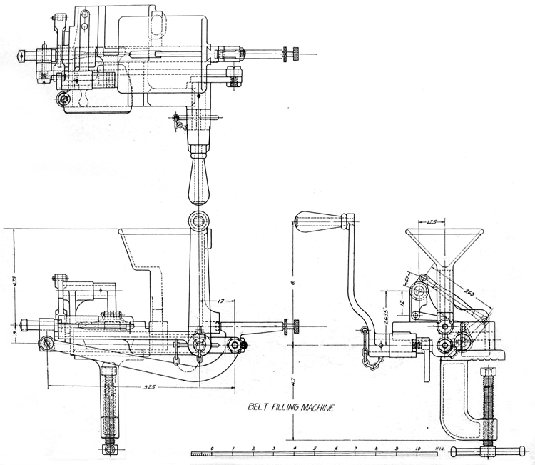
Plate IV. Belt-filling machine
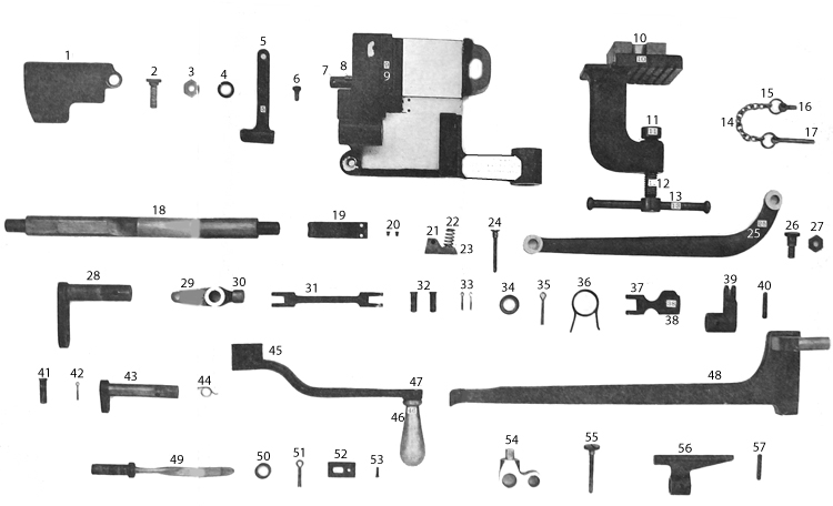
Plate V. Component parts of belt-filling machine
The belt-filling machine is for inserting the cartridges into the belts rapidly and evenly.
SERIAL LIST OF COMPONENT PARTS
[Numbers before components refer to numbers shown e components refer to numbers shown on Plate V.]
1. Belt cover.
2. Belt-cover screw.
3. Belt-cover screw nut.
4. Belt-cover split washer.
5. Belt guide.
6. Belt-guide screw.
7. Feed-lever pin.
8. Feed-lever spring screw.
9. Body.
10. Bracket,
11. Clamp-screw collar.
12. Clamp screw.
13. Clamp-serew handle.
14. Brass chain.
15. Brass-chain split rings (2).
16. Brnss-chain eyebolt.
17. Brass-chain split pin.
18. Cam shaft.
19. Cartridge-guide spring.
20. Cartridge-guide spring screws (2).
21. Catch.
22. Catch spring.
23. Catch-spring rivet.
24. Catch pin.
25. Connecting rod.
26. Connecting-rod screw.
27. Connecting-rod screw nut.
28, Crank.
29. Feed lever.
30. Feed-lever roller.
31. Feed-lever connecting rod.
32. Feed-lever connecting rod pins (2).
33. Feed-lever connecting-rod pin split pins
(2).
34. Feed-lever pin collar.
35. Feed-lever pin split pin.
36. Feed-lever spring.
37. Feed pawl.
38. Feed-pawl lifting knob.
39. Feed-pawl lever.
40. Feed-pawl lever taper pin.
41. Feed-pawl pin.
42. Feed-pawl pin split pin.
43. Feed-yawl lever shaft.
44. Feed-pawl spring.
45. Handle.
46. Handle sleeve.
47. Handle stem.
48. Hopper.
49. Plunge.
50. Plunger washer.
51. Plunger split pin.
52. Plunger guide.
53. Plunger-guide screw.
54. Plunger holder.
55. Plunger-holder screw.
56. Separator.
57. Separator taper pin.
58. Handle key (not shown).
59. Separator screw (not shown),
60. Separator screw head (not shown).
61. Separator check nut (not shown).
DESCRIPTION
It consists of an aluminum body to which the other parts ar assembled, a hopper or vertical guide into which the cartridges a/ stripped from the clips by hand, a bracket by which the machine is attached to the edge of a table or board, and a crank handle for operating.
The surfaces of the body over which the belt travels are faced with steel plates, and the holes for the different shafts are bushed with bronze.
The principal parts which are assembled to the body are the crank the connecting rod, the plunger holder, plunger, cam shaft, separator^ feed lever, feed-pawl lever, feed-pawl lever shaft, feed pawl, and belt guide. On its underside is a dovetailed seat in which the bracket slips and is secured by a spring catch.
The hopper is a vertical bronze trough attached to the body by a lug on its lower end, which fits into a seat in the body. At its upper end it is shaped to receive the cartridge clip and is provided with vertical ribs, which engage in the cannelures in the cartridge cases and retain them as thej' are stripped from the clips. The cartridges are fed down by gravity to the separator, which inserts them successively in the belt.
The bracket is a bronze casting, on the upper part of which is a projecting undercut lug which slips into the seat in the body. The lower part is L-shaped and carries a clamping screw, by which the machine is attached to a suitable support.
The mechanism is operated by the bronze crank handle which is keyed and pinned to the crank. The pin is secured to the crank handle by a chain and eyebolt. The crank is seated in a hole in the body and consists of a short shaft carrying an arm at its inner end, to which is pivoted one end of the connecting rod. The other end of the connecting rod is pivoted to a lug on the plunger holder. This rod is made of bronze and imparts a reciprocating motion to the cam shaft, plunger, and separator.
The plunger holder of bronze is secured to the cam shaft by the plunger-holder screw and has a lug on top which is bored out to form a bearing for the plunger. The latter is of forged steel and consists of a flat blade twisted through an angle of 90° and terminating in a shoulder and cylindrical end, which is held in its bearing in the holder by a collar and split pin. The plunger in its longitudinal movement passes through a rectangular steel guide contained in the body which, on account of the twist in the blade, causes rotation of the latter. The inner end of the blade is rounded and pointed to facilitate its entrance into the loops of the belt. Each loop is opened by the blade before the bullet is forced, into it by the separator.
The separator is a steel arm which is pinned to the. other end of the cam shaft. It engages the head of the lowest cartridge in the hopper and forces it into the loop in the belt just opened by the plunger. The length of the separator is adjusted by means of the separator screw and its parts.
The cam shaft of forged steel is flattened for about 3 inches near the right end. At the inner end of this surface a deep notch is cut in the shaft, the whole forming a bearing which actuates the belt-feeding mechanism.' This mechanism consists of the feed lever of bronze, which is pivoted to the body and carries on its short end a small steel roller, which is pressed against the actuating surface on (he cam shaft by a spiral spring coiled around the hub of the lever. Its other end is connected to an arm on the feed-pawl lever by the feed-lever connecting rod. The feed-pawl lever is pinned on the feed-pawl lever shaft, which is seated in a bearing in a lug formed on top of the body, and the feed pawl is in turn pivoted to an arm on this shaft. The free end of the pawl is roughened so as to engage the belt, with which it is kept in contact by a spring in the pivot joint. The motion imparted to the feed lever by the cam shaft results in a reciprocal motion of the pawl, which feeds the belt forward intermittently.
Over the bullet edge of the belt seat in the body is screwed the belt guide, a leaf spring terminating in a rounded lug, which presses down on the belt and prevents its slipping through the machine. The cartridge-spring guide is another leaf spring secured in a transverse slot in the belt seat and having a groove formed in its free end which aligns the bullet with reference to the loop in the belt. The belt passage in the body is covered by the belt cover, a steel plate pivoted at one side so it can be swung out of the way when inserting or removing the belt.
The belt-filling machine, with its tools and accessories, is packed in the belt-filling machine box.
DIRECTIONS FOR SETTING UP AND USING THE BELT-FILLING MACHINE.
To assemble the machine, first insert the bracket in its seat in the body so that the spring catch in the latter enters its notch in the former. Then securely fasten the machine upon the edge of a table, bench, or other suitable support by means of the clamping screw. Slip the handle on the crank and pin it in place. Turn the handle until it is horizontal, pointing to the left, and, holding it in that position, insert the lug of the hopper in its seat, the groove facing the machine, and press it down until entirely seated.
Swing the belt cover to the left, uncovering the belt passage. Turn the handle so that it points to the right and slightly downward, and, holding the pawl up with one hand, push the end of the belt through the passage with the other, the projecting brass strips points the Uft, until the first loop is opposite the plunger. Then let down the pawl and swing the belt cover into place over the belt. Fill the hopper with cartridges by stripping them from the clips directly into the hopper. By turning the handle the cartridges will be inserted successively in the loops.
In operating the machine it will occasionally happen, due to in equalities in the belt or slipping of the pawl, that a loop will not b fed so that the plunger can enter. In that case the feed pawl should be lifted and the belt adjusted in the proper position. If the plunger catches on the edge of the belt or passes over it, the loop should^be opened by means of the hooked end of the clearing tool.
The feeding of the cartridges from the hopper is sometimes interrupted by a wedging of the column. When this occurs a slight tapping of the hopper will usually correct it.
To insure efficient working of the machine, all bearings should be kept clean and properly oiled. After using, all bright parts should be carefully cleaned and wiped with an oiled rag before replacing the machine in its box.
BELT-FILLING MACHINE BOX.
This box is used for carrying the belt-filling machine and other tools and spare parts. It is similar to the ammunition box in size and construction. Packing is located on the inside to suit the various articles carried.
To distinguish it from other boxes, it has a red band, 1 inch wide, painted longitudinally around the box.
TOOL BOX.
This box carries tools and accessories and spare parts of the guns. It is of the same general construction and has fastenings similar to the ammunition box. It has packing on the inside to suit the articles carried.
To distinguish it from the other similar boxes, it has a blue bund, 1 inch wide, painted longitudinally around the box.
WATER BOX.
The water box is similar in size to the other boxes, but has no lid-In its top is located a screw cap by means of which the water is Put in and taken out of the box. Its russet-leather handle and screw cap are recessed so as to be flush with the surface. To distinguish it from other boxes, it has a white band, 1 inch wide, painted longitudinally around the box.
STEAM-CONDENSING DEVICE.
This device is used to condense the steam generated in the water jacket and to prevent its being seen when emitting from the water-jacket cap escape hole.
It consists of rubber tubing held to the water jacket bj7 means of the supporting band. The tubing is connected to the band by a chain and holder. On one end of the tube is a nozzle which fits the steam-escape hole in the water-jacket cap. With the nozzle in place and the other end running into one of the filled water boxes, the steam passing out of the water jacket is condensed.
PACKING CHEST.
A packing chest is supplied each gun for its safe-keeping in store or whenever dismounted. It holds a gun and tripod, with cleaning rod and spare barrel, a tool box, a water box, and a belt-filling machine box.
PART II. PACK HARNESS.
[Plates VI, VII, and VIII.]
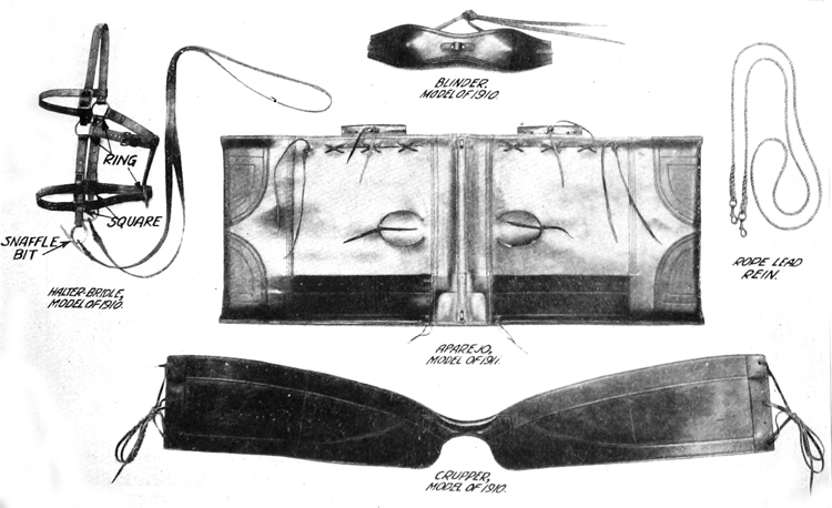
Plate VI. Pack harness.
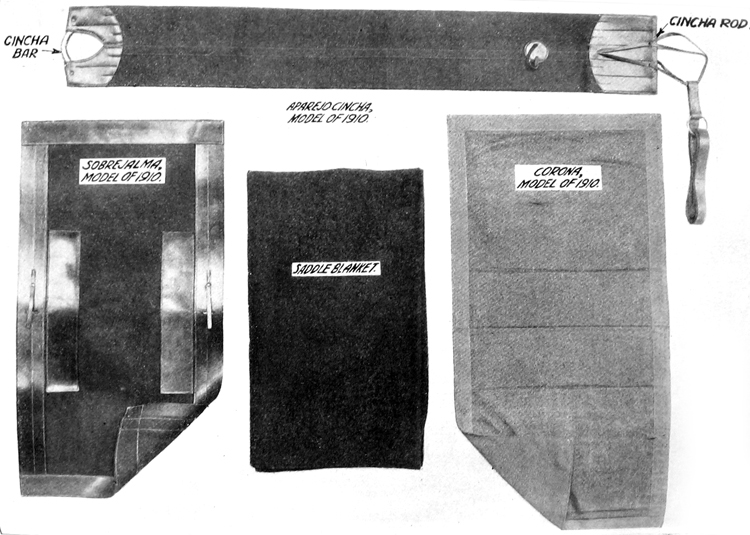
Plate VII. Pack harness.
The group of parts of the pack outfit used for leading the animal and currying the load with its special holders is called the "pack harness." It consists of the blinder, halter bridle, corona, saddle blanket, aparejo, sobrejalma, crupper, and aparejo cincha.
These parts are common to all aparejo outfits and may be used without special frames for packing bundles and boxes.
BLINDER, MODEL OF 1910.
A pack mule is ordinarily blinded during harnessing and unharnessing, loading and unloading. The blinder consists of a centerpiece and two end pieces of russet harness leather with reinforce pieces stitched around the edges and over the joints, the whole shaped to fit closely around the animal's eyes. When not in use, the blinder is ordinarily carried over the packer's shoulder.
HALTER BRIDLE, MODEL OF 1910.
This article is designed to furnish a light, strong head harness for a mule. When leading the animal on the march the bit and its straps are removed from the headstall and fastened to any convenient place on the pack frame. The two snaps of the lead rein are then fastened to the floating ring, the body of the rein forming a loop convenient for holding in the hand.
In riding the animal the lead rein is used in combination with the bit, headstall, and bit straps as a bridle.
When a mule is picketed to a line the lead rein serves as a halter strap.
The bit is made of nickel steel to prevent rusting.
CORONA, MODEL OF 1910.
The corona is the first piece of harness placed on the mule's back-It is a saddle pad made of four thicknesses of good quality gray flan-nel, protected from sweat by a lining of cotton duck. The corona is made in three sizes, and each size is stenciled on the underside to correspond with the size of the aparejo it is intended to accompany-The width is 26 inches for all sizes. In placing the corona it is laid veil forward on the mule's back, canvas side down, and then slid to the rear until its front edge is just behind the point of the withers, are being taken that the hair lies smooth beneath it.
When manufactured in quantity, 10 per cent are 48-inch, 15 per cent 50-inch, and 75 per cent 52-inch.
THE SADDLE BLANKET.
The saddle blanket forms additional padding under the aparejo. It is carried under the aparejo and over the corona.
The blanket is made of pure wool of olive-drab shade with an olive-brown border of two stripes. The blankets are rectangular, 72 by 84 inches. Each blanket has the letters " U. S." and the bursting shell located in the center.
APAREJO, MODEL OF 1911.
This article consists of an aparejo body and one aparejo frame. The aparejo body is made of two rectangular pieces of leather (back and belly pieces) sewed together along the edges and through the middle, forming two pouches. The edges, the middle seams, and particularly the ends are reinforced with heavy leather facings. Handholes for stuffing are left in the belly pieces, and holes and slits laced with thongs are made in the back pieces so that the frame, or parts of it, may be inserted, removed, or replaced. The carrier pieces and front facing have lacing holes for the attachment and adjustment of the crupper. Two steel chock staples attach the sobre-jalma and pack frame to the aparejo. The rib sticks are furnished longer than necessary and should be sawed off to the proper length after the boot and top sticks are firmly rammed home. The first three sticks (starting at the front) are of uniform thickness; the remainder are tapered to give the rear of the aparejo more flexibility than the front. The sticks are stamped and are intended to be arranged in a gradually diminishing thickness.
Cloth is tacked to the top stick to prevent the hay from slipping down.
Note.—Aparejos are issued to the service with ribs in place. They
are furnished in 58, 60, and 62 inch sizes, as follows: 10 per cent
58-inch, 15 per cent 60-inch, and 75 per cent 62-inch. Should repairs
or alterations make it necessary to rib up, the butt of the fifth rib is
seated in its slot, the overlap at its slot in the top stick is marked
and cut away, and the other ribs are cut to the exact resulting length.
SOBREJALMA, MODEL OF 1910.
This article is a waterproof and wear-reducing covering for the aPMej0. It is made of one thickness of heavy cotton duck, faced around the edges on the upper side with collar leather. Two leather reinforces are placed on the upper side to protect the duck from th wear of the load. Holes are provided through which the chock staples of the aparejo protrude; chock straps passing through the* chock staples hold the sobrejalma and pack frame on the apaveio Supporting caps at both ends of the end facings hold the supporting sticks in place. Sobrejalmas are made in three sizes, and when manufactured in quantity 10 per cent of 50-inch, 15 per cent 58-inch and 75 per cent 60-inch. The size stamped on the sobrejalma is the size of the aparejo for which it is suited.
CRUPPER, MODEL OF 1910.
The crupper is made of russet collar leather, shaped (and padded in the middle) to fit the animal. The side pieces extend forward across the aparejo, and are laced to it in front and held up at rear by latigo-leather thongs. The depth of the side pieces affords a broad surface to bear against the animal and also prevents the crupper from sagging. The side pieces are reinforced around their edges with leather, and those which come in contact with the animal's flanks are lined with duck. Cruppers are made in one size only, 78 inches long.
APAREJO CINCHA, MODEL OF 1910.
The aparejo cincha is 10 inches wide and is made of cotton duck, folded and stitched along the middle. Both ends are faced with leather, and the end to which the cincha strap is fastened carries a jSj-ineh steel rod in the fold of the lacing-end piece, while the other end has a curved piece of gas pipe (cincha bar). Fifteen inches from the strap end of the cincha a leather thong (finger loop) is attached, which is used to carry the slack of the cincha strap. The cincha strap is of harness leather and has a rendering ring at one end; this end is attached to the cincha body by a latigo-leather thong. The metal parts are either of bronze or are copper plated to prevent rotting of the leather. The cincha is made in three sizes, and when manufactured in quantity 10 per cent are 68-inch, 15 per cent 70-ineh, and 75 per cent 72-inch. The size stamped on the cincha is the size of the aparejo for which it is designed; the cincha body is 10 inches longer than the corresponding aparejo.
INSTRUCTIONS FOR SETTING UP THE APABEJO.
To rib up.—Unlace the slits and handholes; soak the aparejo in tepid water for about 15 minutes; drain it and lay flat, back pieces up; insert the boot stick and the top stick through the slit in rear and press them to their places at the boot and the center stitch line> slotted sides up; insert the numbered set of nine ribs through thfc slit in rear in their numerical order and seat them in that order from
collar to rear in the slots of the boot stick and top stick, butts at the boot; secure the top of each rib as it is seated by inserting the aparejo key at the front edge below the collar and passing it over the rib in place; fasten the key bar to the collar by the thong.
Note.—The aparejo after being set up should under no circumstances be allowed to dry in the sun.
To fill or pad.—Turn the aparejo over, belly pieces up; procure about 6 pounds of long, fine, soft, elastic hay; taking a little at a time, tease or " mix " it carefully; insert it through the handhole and thus gradually fill the body of the aparejo with a smooth and even layer, not more than 2 inches thick.
Note.—Other filling may be used in necessity, such as moss, excelsior, curled hair, or sea grass; but these substitutes are difficult of manipulation in alterations necessary to accommodate the rigging to injuries of the mule. By teasing or " mixing " is meant the arrangement of the stalks of the hay so that they will cross one another. The body of the aparejo is that part which comes in contact with'the body of the mule. As 3 inches of the lower portion of each boot stick and 3 inches of the upper portion of each top stick must not come into contact with tho mule, no filling should be pressed under the boot stick or within 3 inches of the center of the stitch line. The body course tapers, however, so as to overlap the boot stick and saddle bar. and also tapers toward front and rear.
To face or dress.—To adjust the aparejo more accurately to the shape of the mule, introduce filling and press it well into the corner of the front boot; working toward the handhole, continue the facing along the boot stick and front edge, gradually increasing its thickness to about 1 inch at 7 inches from the corner "and forming its inner edge into the arc of a circle concentric with the handhole, the thickness tapering to the ends of the arc; continue this for 3 inches more toward the Tiandhole, rapidly decreasing the thickness to nothing. Proceed in exactly the same way at the collar; under no circumstances should the collar facing reach within 7 inches of the center of the handhole. Connect the front boot and collar facings by a dressing along the front edge about 3 inches wide and 1 inch thick, decreasing in thickness toward the handhole and toward the middle of the edge.
Note.—In facing up, introduce the filling with the palm of the hand up, so as not to disturb the body course. In case the leather will not yield enough to permit the filling to be introduced well into the corners, a tamping stick may be used to raise it. This stick, used with the commercial aparejo, is i or 5 feet long, 1J inches in diameter, wedse-shaped for 4 inches from one end, the edge of the wedge being about i inch thick and grooved. The object of the boot facing is to cause the boot stick to carry horizontally and parallel to the center of the mule and to give free action to the mule's elbow. Mules of large barrel will require a thicker facing than described. The object of the collar facing is to cause the saddle bar to carry horizontally and parallel with the center of the mule and to protect the mule', withers. Mules with high withers will require a thicker facing than that described. In setting to the shape of the mule, the aparejo bends at the middle of the front edge. It is important that the body course remain undisturbed during dressing, and that the instruc-tions given be carefully followed to avoid sore withers or tails and body or belly bunches.
To attach the crupper.—Stand the aparejo on its boots in its normal position; secure a lace thong to the front hole on the upper facing of the crupper on each side and fasten the crupper with short thongs to the center holes of the carrier pieces on the rear of the aparejo; pass the crupper lace thong through the second hole from the top of the front "facing of the aparejo, through the second hole of the crupper, through the third hole of the aparejo facing, through the fourth hole of the crupper, and so on, finishing through the bottom holes of the facing and crupper and tying to the crupper hole.
Note.—In lacing the crupper to the aparejo, the thong must be passed through the holes from the outside and must not be twisted, the lacing must not cross, and it is important that the tie be made on the last hole of the crupper instead of the aparejo.
Guayaba, willow, dogwood, hickory, or any other wood combining the qualities of permanent elasticity and strength may be used to replace broken ribs. When the set-up aparejo is to be filled, no soaking is necessary; instead, the belly pieces are made pliable by rubbing with a sponge.
Mules weighing 850' to 900 pounds require a 58-inch aparejo; 1,000 pounds, 60-inch; 1,100 pounds, 62-inch.
When the mule is loaded, the cincha, in travel, should free the elbow by about 1 inch; more than this will prevent a proper grip on the belly.
If the boots ride high enough on the body of the mule, or if they reach under the belly, even though they ride horizontally and parallel to the center of the mule, the aparejo will be likely to turn easily. This fault encourages injuriously tight cinching.
If one or both boots flare out or turn in toward the mule, cinch sores, sore tails, or belly bunches are caused.
The width of the collar-arch clearance should be at least 5J inches. If it is too narrow or too wide, or if the saddle bars slope downward toward the front, there will be sores on the withers; if they slope to the rear, there will be injuries over the loins called " kidney sores."
If the lacing of the crupper is drawn too tight at the bottom, the lower edge of the .cruper will rub the buttocks and cause abrasions.
The obiect to be attained is the uniform distribution of the weight of a load ovr that portion of the mule's body which is anatonncal y uitedto the carrying of a burden, so that the saddle will nde with little motion and without friction of the bearing surface on the body. The contact of the bearing surface of the saddle must be close at all points As the mule's body swells from front to rear, the more or less cylindrical^ shaped aparejo, after the body course is laid, must be modified by facing up so as to provide a concave surface to fit over the convex surface. But, as the barrel of the properly conformed mule is nearly cylindrical through the rear half or more of the contact surface, no facing, as a rule, is necessary in the rear part of the aparejo, although conformation may require it occasionally. The above instructions were prescribed by H. W. Daly, chief packmaster, Quartermaster Corps.
CARE OR RUSSET LEATHER.
Leather equipments which have become wet should be dried in the shade. Wet leather exposed to the direct rays of the sun or to the heat of a stove or radiator becomes hard and brittle.
When russet-leather equipments become soiled in service they should be cleaned by carefully washing the leather with a sponge moistened with a heavy lather made of clean water and castile or Miller's soap, and then rubbing vigorously with a dry cloth until the leather is completely dry.
If the leather becomes harsh, dry, and brittle from exposure to water or other causes, clean as above described, and while the leather is still slightly moist apply an exceedingly light coat of neat's-foot oil by rubbing with a soft cloth moistened (not saturated) with the ou. If it is found that too much oil has been used, the surplus can be readily removed by rubbing with a sponge moistened with naphtha or gasoline. But these oils are not issued for this purpose.
Where a polish is desired, the leather should first be thoroughly cleaned, and then the leather polish or dressing supplied by the Ordnance Department should be applied sparingly and thoroughly rubbed in with a soft, dry cloth. Scars, cuts, or abrasions of the leather may be improved in appearance but not obliterated by similar use of the leather polish.
Kusset leather may be cleaned, oiled, and polished as described
above, but it should be noted that if more than a light coat of oil be
given the leather will be greatly darkened and will quickly soil the
clothing. No method of craning will restore the original light color ofe leather or remove stains or discolorations.
PART III. SPECIAL PACK EQUIPMENT.
[Plate XVI.]
This equipment includes the following:
Pack frame.
Ammunition hanger.
Gun hunger.
Gun case.
Tripod hanger.
Spare-barrel ease.
Broad-hntchet head case.
Rigging cover.
Picket pin and eye.
Picket-pin carrier.
Picket-rope section.
Thongs.
Implement strap.
Filling-cup strap.
Plates IX to XV, inclusive, show the special pack equipment, with their loads attached, placed on the pack harness for the first section of five mules. The loads for the second sections are similar to the first except as shown in the table of equipment.
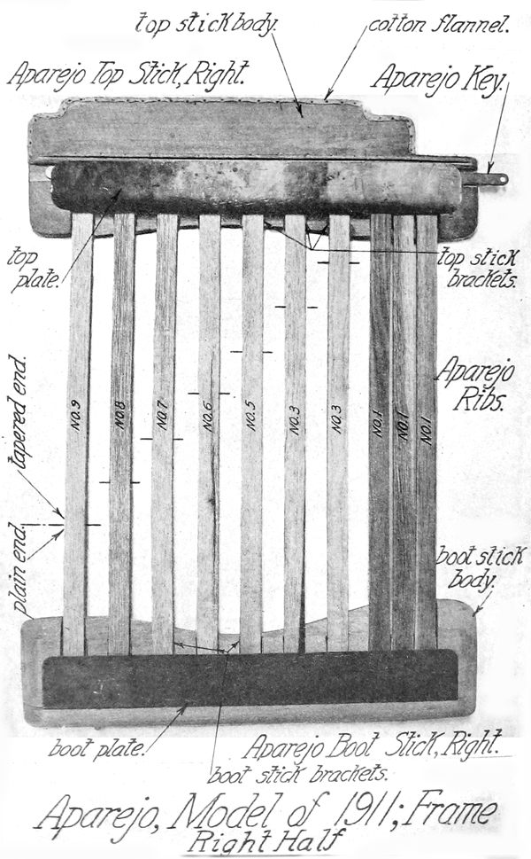
Plate VIII. Aparejo, Model 1911, frame (right half)
PACK FRAME.
This article consists of a framework built up of wood and metal to carry the weight of the load and distribute it uniformly over the carrying surface of the aparejo. It is arranged to suit the load to be carried. To the top of the pack frame are attached four bronze castings, known as superframes, which, when folded up, form a flat surface for carrying boxes or packages which have flat sides, or, when folded down, form a convenient receptacle to hold picket pins, shovels, picket ropes, or other items of a similar nature. Four steel-loop clevises with straps are fastened to the top of the pack frame, furnishing means of lashing articles to the frame. The steel arches, with the bronze superframes, are interchangeable and may be removed by withdrawal of the steel pins. The sides of the pack frames are riveted together. The hook hinges are made of forged steel and are arranged for hanging boxes or hangers on the sides of the pack frame. Four pack-frame staples are fastened to the brace bar and are used for holding down side loads.
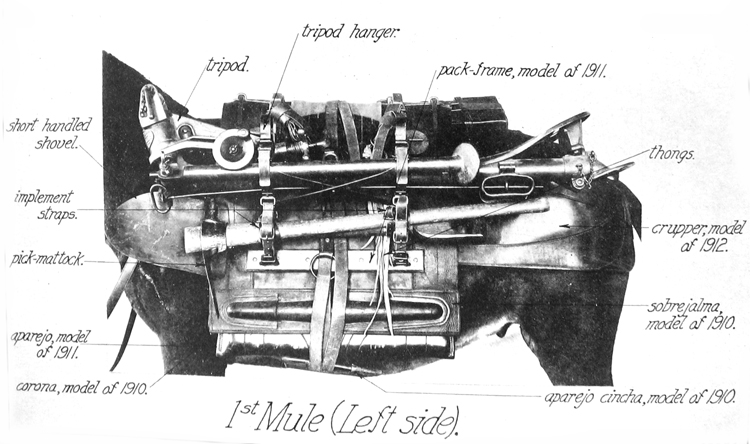
Plate IX. Pack, first mule (Left Side)
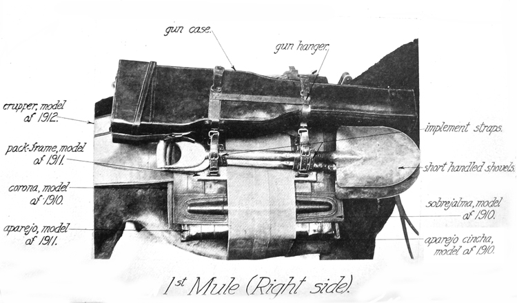
Plate X. Pack, first mule (right side)
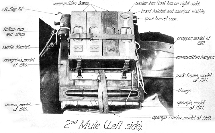
Plate XI. Pack, second mule (left side)
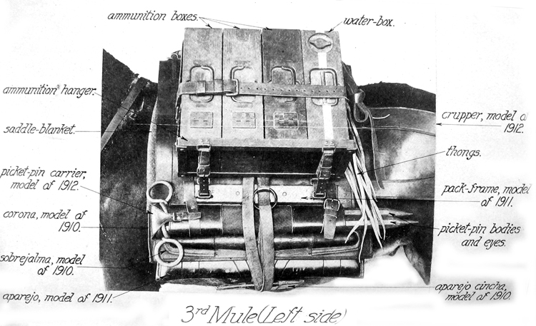
Plate XII. Pack, third mule (left side)
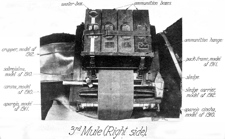
Plate XIII. Pack, third mule (right side)
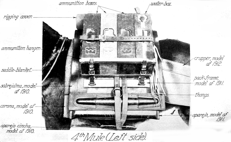
Plate XIV. Pack, fourth mule (left side)
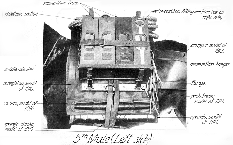
Plate XV. Pack, fifth mule (left side)
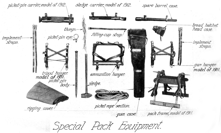
Plate XVI. Special pack equipment
AMMUNITION HANGER.
This article consists of a light steel frame for carrying ammunitio boxes. The steel loops at the top of the hanger are elongated to facilitate attaching the hanger to the pack frame. The straps on to° which lash the boxes in place are provided with quick-release devices Straps with quick-release devices are provided to fasten the hanger to the pack frame.
GUN HANGER, MODEL OP 1911.
This article consists of a steel frame for carrying the gun in its case. The gun-hanger frame limb, rear, is braced, with the gun-hanger case rest, by the gun-hanger lateral brace in front and the two diagonal braces, crossing each other, in the rear. The gun-hanger riser is riveted to the frame limb rear. Hanger eyes riveted to the rear of the frame afford means of hanging the frame to the pack. The gun case is held in position on the hanger by the gun-case straps. Straps and strap fasteners on the underside of the hanger afford means for carrying several tools. A number of gun hangers, model of 1910, have been made and will be issued until the supply is exhausted.
GUN CASE.
This case is made of sole leather and is to protect the gun in transportation and from the weather. It is arranged in such a way that the gun may be removed with the greatest ease and rapidity. The small end of the case has an asbestos pad riveted to the end plate and four thicknesses of leather sewed and riveted to the top and side plates for holding the water jacket from ramming the nozzle against the end plate. A long and a short guard are riveted to the sides and bottom of the case, which strengthen the case and also prevent the leather from coming in contact with the metal guri hanger. The large end of the case is reinforced around its outer edge. The cover fits over this reinforce and is itself reinforced around the edge. The cover is secured to the case by the gun-case cover strap riveted to the cover and held to the bottom of the case by a chape and buckle and to the top by a quick-release device.
TRIPOD HANGER, MODEL OF 1913.
The tripod hanger for securing the tripod in pack consists of a front and rear tripod-hanger frame limb braced together on the back and bottom by diagonal braces. The frame limb, front, has riveted to it the tripod rest, front, on the end of which is pivoted the tripod-hanger clamp hook; and the clamp pivot clip, front, on which is hinged the tripod-hanger clamp with the tripod retaineB riveted thereto. The frame limb, rear, has riveted to it the tripod rest, rear, on the end of which is pivoted the clamp hook; and the clamp-pivot clip, rear, on which is hinged the tripod-hanger clamp with the tripod-bearing block and tripod-bearing spring riveted thereto. Hanger eyes riveted to the rear of the frame limbs afford means for attaching the hanger to the pack frame. A number of tripod hangers, model of 1910, have been made and will be issued until the supply is exhausted.
SPARE-BARBEL CASE.
This case is a leather cover reinforced by the end case tip at the closed end and the mouth collar at the open end to make neat fits for the ends of the spare barrel. The open end is closed by the cover, having a strap around it secured to the body by rivets on one side and by a billet on the other. Two case straps, riveted to the case, are used to secure the case in pack.
BROAD-HATCHET-HEAD CASE.
This case, as its name implies, is designed to protect the head of the broad hatchet, and affords a convenient means of carying that tool A strap with a ring is riveted to the flap of the case to form a convenient means of lashing the broad hatchet to the top load of the pack.
RIGGING COVER.
The rigging cover, made of olive-drab duck, is 43 inches wide and 17 feet long.
PICKET PIN AND EYE.
The picket pin and eye are made of steel. One picket pin and eye is furnished each section, but both are carried on the same mule.
PICKET-PIN CARRIER.
This article has a cotton-duck body, with two russet-leather end pieces for reinforces. One end is smaller and two pins are placed with their points through this. They are held securely by a flap coming across the other end. A loop strap on one end and a billet and buckle on the other end secures the carrier to the pack.
PICKET-ROPE SECTION.
This article consists of a 1-inch diametermanila rope, 25 feet long, with a loop spliced on each end. It is designed to be stretched along 'he ground and fastened at the ends with pins. The animals can then be fastened by means of their halter-bridle reins to this rope Ir> the usual way. Three picket-rope sections are provided for each company or troop. Two sections of rope can be fastened together by means of the loops and a pin driven at each end. If it is necessary to use the sections separately, a shovel or pick mattock could be used as a " dead man."
IMPLEMENT STEAP.
four implement straps, two 22 inches long and two 30 inches long, are used to secure the pick mattock and the shovels to the pack.
STRAP FOE FILLING CUP.
This strap is similar to the gun-case straps and is used to fasten the filling cup to the top load of the pack.
PART IV. PIONEER TOOLS.
Broad hatchets 2
Pick mattocks 2
Short-handled shovels 6
Rule, 2 feet 1
These tools are commercial articles. The broad hatchets, pick mattocks, and shovels are carried on the different packs strapped as shown in Plates IX, X, and XI and in the list of total equipment. The 2-foot rule is carried by personnel.
PART V. EQUIPMENT OF ONE MACHINE-GUN COMPANY OR TROOP.
The following table [not shown - AllWorldWars] sets forth the total equipment of one machine-gun company or troop armed with the Maxim automatic machine gun, caliber .30, model of 190-i. It shows, in general, where each article should be carried, but the commander may use his discretion as to the disposition of articles for which no particular fitting or receptacle is provided.
In making requisitions for any of these parts the names used should be those used in this table, or on the plates, or in the descriptive matter of this handbook. If an article is wanted which is not shown as a whole but shown as made up of component parts, these component parts should be stated.
PART VI. ADDITIONAL MATERIEL PERTAINING TO THE MAXIM AUTOMATIC MACHINE GUN BUT NOT TO A MACHINE-GUN COMPANY OR TROOP.
DESCRIPTION OF THE WHEELED MOUNT, MODEL OF 1905 p01, MAXIM AUTOMATIC MACHINE GUN, CALIBEB .30, MODEL 0J 1904.
GENERAL DESCRIPTION.
The wheeled mount is intended for use in and around seacoast fortifications and is designed to afford easy transportation of the gun and a sufficient supply of ammunition, together with the tools required for quick exchange of damaged parts, spare parts, and a water box. It carries 1,500 rounds of ammunition in belts, packed in' 6 wooden ammunition boxes, each holding one belt containing 250 cartridges. The tool and water boxes are the same as those furnished for the pack outfit. The carriage is to be dragged by hand by six men, and for this purpose a wooden handle bar and a drag rope with handle loops are attached to the end of the trail.
DETAILED DESCRIPTION.
[Plate XVII.]
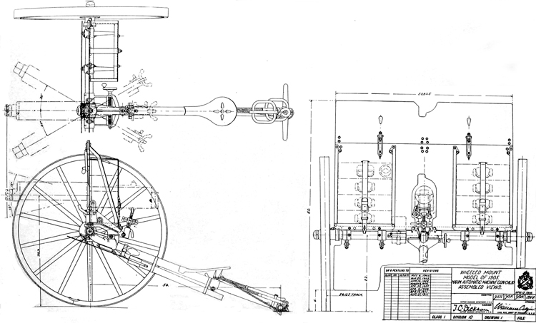
Plate XVII. Assembled views of wheeled mount
The wheeled mount consists of the following principal parts: Axle, , trail, trail shoe, seat, wheels, pintle, brackets, ammunition carriers, shield, apron, top carriage, traversing arm, traversing mechanism, elevating mechanism, drag rope, and trail handle.
THE AXLE.
This consists of a length of steel tubing in each end of which is shrunk and pinned a steel axle arm. At its center the tube supports the pintle and on each side of the center the brackets for the ammunition, tool, and water boxes. These parts are all attached by means of sleeves which slip over the tube from the ends and are secured U1 position by pins. On the left side of the pintle a sheet-steel frame is clamped to the axle to hold the filling cup.
THE TRAIL.
The trail is made of a drawn-steel tubing, the forward end of whicn is inserted and pinned into a sleeve formed on the pintle casting-The lower end is similarly fastened over a shank on the trail shoe-The trail supports the seat, the front end of which is formed around the trail tube; the rear is held by a sliding clamp bracket.
THE TRAIL SHOE.
This is a steel casting attached to the rear end of the trail tube and is shaped to provide a small spade to prevent movement of the carriage to the rear in firing, a float to give increased surface support to the shoe, and a trarisverse sleeve through which the trail handle passes. In rear of this sleeve is formed an eye, to which the drag rope is attached by means of a clevis and pin.
THE SEAT.
The seat is formed of flange steel and is similar to the one on the tripod mount. Its front end is formed to fit around the trail tube, and it is secured to the tube at its rear end by the seat bracket and clamp, which permits a sliding adjustment of the seat on the trail to suit the gunner.
THE WHEELS.
The wheels are of the Archibald pattern, 44 inches in diameter, with tires 2.5 inches wide. The outer end of the hub is closed by a hub cap containing a dust-proof oil hole, and the wheels are secured to the axle on the inner side by hinge bronze fasteners, which lock the hubs to collars on the axle. These fasteners are held in place by a hasp and split pin.
THE PINTLE.
This is a steel casting differing in shape from the same piece in the tripod mount in a few minor points only. One is that the lugs in the latter to which the legs are attached are replaced by a sleeve bored out to fit closely over the axle tube. Lateral movement of the pintle on the axle tube is prevented by four taper pins which pass completely through and are retained in place by split pins. Another point of difference is that the seat for the traversing screw is made longer, so that the gun can be given a total traverse of 30° on either side of its axis. On each side of the pintle seat is a split lug for the attachment of the shield, and on the'lower side of the trail sleeve is a lug to which the apron toggle brace is hinged. Through the front of the pintle is drilled a hole, through which the cleaning rod is inserted into the trail tube for transportation. The rod is held in position by a strap attached to the pintle by a clevis.
BRACKETS.
The brackets are four in number, two right hand and two left. > They are steel castings consisting of a sleeve bored out to fit closely over the axle tube, an arm extending to the rear to form a support for the ammunition carrier, a split lug on top to which the shield Js bolted, and a lug projecting downward and forward to form a hinge for the apron. The brackets are arranged in pairs on the axle en each side of the pintle and are secured against movement by taper Pins and split pins similar to the pintle attachment.
AMMUNITION CARRIERBS.
The ammunition, tool, and water boxes are supported on eith side of the pintle by the brackets, ammunition carriers, and shield The carriers consist of steel angles bent so as to form three sides of rectangle. The upper free ends of the carriers are riveted to the mai* shield and their lower closed ends bolted to the arms of the brackets The carriers thus form braces'for the shield in addition to serving as end supports for the columns of boxes. Each carrier contains four boxes, stacked on their sides and retained in this position by a leather strap which passes through a loop riveted to the rear face of the shield and is secured to the carrier at the bottom by a hasp and turn-buckle. The lower box rests in front upon a steed angle riveted to the lower edge of the shield and in rear upon the horizontal flange of the carrier.
SHIELD AND APKON.
For protection of the gunner and ammunition against small-arm fire the mount is provided with a shield which closes practically all the space between the wheels above the axle, and an apron which performs the same function below the axle. Both shield and apron are made of hardened steel plate 0.2 inch thick. The shield consists of two parts, the main shield and the top shield. The former is rigidly secured along its lower edge by bolts through lugs in the brackets and pintle and is braced near its upper edge by the ammunition carriers. It is cut away sufficiently at the center to fit over the gun and top mount and to permit easy sighting. To give convenient access to the filling valve of the water jacket on the gun, which is located in front of the shield, an extension piece is attached to the cap seat of the valve on guns used with this mount, which leads back through the cut in the shield far enough to allow the use of the filling cup in rear of the shield. The top shield is hinged to the upper edge of the main shield and is provided with two turnbuclde fastenings by which it can be secured both in the erect and folded positions. For transportation the top shield is folded down to the front, its upper edge being cut out at the center to avoid striking the gun in this position.
The apron is hinged to lugs on the brackets near its upper edge. I* projects above the hinges sufficiently to overlap the lower edge of the main shield, thus protecting the axle, and is braced in position by a toggle brace secured to the underside of the pintle sleeve for the trail. The apron can be folded back against the underside of the trail for transportation and is held in that position by a strap which passes round the trail and through two loops riveted to the apron.
TOP CARRIAGE AND ELEVATING MECHANISM.
The top carriage and elevating mechanism for the wheeled mount are practically identical with the same parts as used on the tripo"
and can be used on the latter. The only material difference is that the hub of the top carriage for the wheeled mount has flattened sides to which are screwed the ends of a bent steel frame forming a depression stop.
TRAVERSING MECHANISM.
The traversing mechanism differs from that on the tripod only in having a traversing screw about 2.9 inches longer, permitting a traverse of 80° on each side of the axis. The traversing arm is also the same as for the tripod, except that the annular slots for the traversing clamp bolt and the length of the seat for the traversing nut block are longer to permit the greater traverse. But one traversing handwheel is used.
DRAG ROPE AND TRAIL HANDLE.
The trail handle is a wooden bar which passes through a sleeve formed in the trail shoe. The drag rope is attached to the trail shoe by means of a clevis and bolt and is provided with handle loops for four men. Six men. four on the drag rope and two on the handle bar, are sufficient to drag the gun and mount completely equipped over all ordinary ground. When not in use the drag rope is wound between a hook in the rear of the seat clamp and the handle bar and is secured by a strap.
OPERATION.
The directions for mounting the gun on this wheeled mount are the same as those given for this operation on the tripod.
The wheels are oiled by pressing in the spring valve in the dust cap with the spout of an oil can and allowing a small amount of oil to run in. It is not necessary to remove the wheels except for cleaning.