Slave to the Game
Online Gaming Community
Description of Telescopic Musket Sights Model 1908 - 1913
No. 1957
DESCRIPTION
OF
TELESCOPIC MUSKET SIGHTS
MODELS OF 1908 AND 1913
(FOUR PLATES)
DECEMBER 14, 1908 REVISED JULY 22, 1912 REVISED NOVEMBER 18, 1915
WAR DEPARTMENT, OFFICE OF THE CHIEF OF ORDNANCE,
Washington, November 18, 1915.
This manual is published for the information and government of the Regular Army and Organized Militia of the United States. By order of the Secretary of War:
WILLIAM CKOZIEE. Brigadier General, Chief of Ordnance.
DESCRIPTION OF TELESCOPIC MUSKET SIGHTS.
MODEL OF 1908.
1. Throughout this description frequent reference is made by
number to the photographs Plate I and to the sectional drawings
Plate II. On either plate a given number refers to the same part of
. the instrument. A nomenclature table, arranged in sequence of the
reference numbers, will also be found on page 7.
2. The telescopic musket sight consists of three essential parts the
telescope, indicated by numbers 1-11 and 20-28. (51-62, Plate I. the
lever (50-60), on which the telescope is mounted by a vertical axis
and the slide (30-39). to which the lever is secured by a horizontal
axis, while graduated dials provide means for turning the instrument
on both of these axes.
THE TELESCOPE.
3. In the telescope body (1) (see PI. II) is mounted the objective
cell (10) for the objective (9), which has a clear aperture of i{[ inch,
a focal length of 7 inches, and gives, with the eyepiece, a power of 6
diameters and a field of 44°. The telescope is provided with Porro
erecting prisms (21) (21), mounted in accurately milled recesses in
the prism holder (20) and held in place under constant pressure by
the prism cap springs (23) of the prism caps (22) (24), the caps being
fastened by the prism cap screws (25). The telescope has a reticule
holder (2) into which is spun the glass reticule (3). on which are
etched vertical and horizontal cross lines and stadia lines, the latter
being so placed that they span the height (5 feet 8 inches) of an aver
age man standing at a distance of 1,000, If00, and MOO yards respectively. The telescope has an eye-lens holder (5) for the Steinheil
triple achromatic eye lens (4). The holder has a long threaded portion by which it is screwed into the body and by which means for
focusing is secured. The eye-lens holder is locked in position by the
focusing lock nut (8) and is provided with an eye cap of soft rubber (6), fastened by the eye-cap ferrule (7). On each telescope is fastened, by means of table screws (28), the wind and range table (61) which shows the ranges corresponding to the three stadia lines.
I The lever (50) supports the telescope body by means of the adjusting screw (58). .This screw forms a vertical axis for the telescope, and the segmental worm gear (A), together with the drift screw (53) and its graduated drift dial (55), provide means for turn¬ing the telescope on this axis for drift and wind corrections.
5. The slide (30) supports the lever (50) on the horizontal axis (C). The pin (D) of the lever engages with the internal hardened steel cam (E) of the range dial (32), and is kept in contact with it by the lever spring (31). The inner circumference of the range dial is conical and fits in a conical bearing, so that it can be clamped in any desired position by tightening the range-dial knob (34) against the keyed range-dial washer (33). By turning the dial (32) the telescope is rotated on the horizontal axis (C), giving the proper depression angle for range correction.
The telescopic sight bracket is assembled to the receiver of the rifle by means of screws. The sight is mounted on the bracket by means of the dovetail (B) in the slide (30) and is held in position by means of the catch (36) which may engage in either of the two notches in the bracket. The catch can be released by pressing the catch nut (38).
ADJUSTMENT OF THE INSTRUMENT.
For focus.—In adjusting the instrument at the factory the reti¬cule is set exactly in the focal plane of the objective, which has a universal focus beyond 100 feet, and the eyepiece is set for the vision of an average observer. Should alteration of the focus of the eye¬piece be necessary to suit special conditions, unscrew the focusing lock nut (8) and screw the eyepiece out or in until the cross lines of the reticule are sharply defined, and until at the same time the image of the target is clearly visible. Then move the head up and down, so that the eye may travel across the eyepiece. If the focus has been correctly found there will be no parallax, that is, no apparent motion of the cross wires with reference to the target when the eye moves across the field. The focus being accurately adjusted, be sure to lock the eye-lens holder by tightening the focusing lock nut (8). The rubber eye cap can now be turned, without affecting the focus, to any desired position. If the rubber cap does not turn easily, loosen the eye-cap ferrule (7) and tighten it again when the adjust¬ment is made.
For elevation.—The range dial is graduated from 0 to 3,000 yards by 20-yard divisions. To make elevation adjustment attach the telescopic sight to the bracket of the rifle, being sure that both the slide and the bracket are perfectly clean, secure the rifle in a fixed rest, and set the service sight of the rifle at 500 yards. Set the range of the telescopic sight at the same range and clamp it. The cross wires of the telescopic sight and the line of sight of the rifle through the service sight should then bisect the target exactly. If the cross wires of the telescopic sight are too high, unscrew the hexagon adjusting-screw nut (59), using the screw driver provided with the sight, and turn the adjusting screw (53) clockwise, which will cause the cross wires to drop on the target. Turning the adjusting screw in the opposite direction will make the cross wires rise. After the adjustment is made be sure to tighten the nut. The rifle is then fired several shots to test elevation, the necessary correction being made by the movement of the adjusting screw until a satisfactory elevation is obtained.
For drift.—The graduations on the drift dial (55) correspond to 1 inch on the target at a range of 100 yards. Turning the dial clock¬wise corrects to the right, as indicated by the letter (R) and counter¬clockwise to the left, as indicated by the letter (L). There are 38 points of left and 46 points of right drift correction. The drift dial should read " 0 " when the optical axis of the instrument is parallel with the bore of the rifle. Should it be necessary to adjust the dial; secure the rifle in a fixed rest, make the optical axis of the instrument parallel with the line of sight through the service sight, by sighting at some distant object, loosen the two drift-dial screws (57) which will permit rotating the dial without moving the drift screw, set the dial exactly at " 0 " and clamp the screws firmly against.
Nomenclature table.
1. Body.
2. Reticule holder.
3. Reticule.
4. Triple eye lens.
5. Triple eye-lens holder.
6. Eye cap.
7. Eye-cap ferrule.
8. Focusing lock nut.
9. Objective.
10. Objective cell.
11. Body screws.
20. Prism holder.
21. Prisms.
22. Prism cap.
23. Prism-cap springs.
24. Prism cap.
25. Prism-cap screws.
26. Wind and range table.
27. Drift table.
2S. Table screws.
30. Slide.
31. Lever spring.
32. Range dial.
33. Range-dial washer.
34. Range-dial knob.
35. Spring cotter (for knob).
36. Catch.
37. Catch spring.
38. Catch nut. .
39. Range-dial washer pin.
50. Lever.
51. Spanner nuts.
52. Spring cotters (for nuts).
53. Drift screw.
54. Drift-screw washer.
55. Drift dial.
56. Drift-dial washer.
57. Drift-dial screws.
58. Adjusting screw.
59. Adjusting-screw nut.
60. Drift-dial pin.
61. Range table.
62. Range-table screws.
70. Screw driver.
POUCH.
Model of 1911 for telescopic musket sights.
The pouch furnished for the telescopic sight is made of russet collar leather. It is provided with a double hook and a leather strap, so that it can be earned either on the cartridge belt or over the shoulder.
MODEL OF 1913.
The telescopic musket sight, model of 1913, is shown on photo¬graphic Plate III. A sectional drawing of the instrument is shown on Plate IV. A nomenclature table, with illustration number, piece mark, and drawing number, will be found below. The illustration numbers given in nomenclature table refer to Plates III and IV.
This instrument is almost identical with the telescopic musket sight, model of 1908, and differs only the following particulars:
(a) The objective (27) is held in the objective cell (24) by the objective retaining ring (25) which is held in place by the objective
retaining nut (26).
(b) The reticule holder (41) is held in the telescope body (5) by
the reticule-holder nut (42), which screws into the telescope body.
The reticule is prevented from turning by the reticule-holder lock
screw (43).
(c) The triple eye-lens holder (50) has a short threaded portion by which it is screwed into the telescope body (5) and by means of which the instrument is focused. To alter the focus, remove the focusing-lock collar cap (21), loosen the focusing-lock collar (19) by unscrewing the focusing-lock collar screw (20), then screw the triple eye-lens holder (50) in or out until the cross lines on the reticule (40) are sharply denned and the image of the target is clearly visible. After the focus has been determined, lock the triple eye-lens holder (50) by screwing the focusing-lock collar screw (20) into the telescope body until the focusing-lock collar bears tightly enough to prevent turning, then replace the focusing-lock collar cap (21). The rubber eye cap (18) can now be turned without affecting the focus of the instrument. If the eye cap (18) does not turn easily, loosen the eye-cap ferrule (17) and tighten again when adjustment is made.
Nomenclature.
Illustration No:
1. Adjusting-screw spanner nut.
2. Adjusting-screw nut.
3. Adjusting screw.
4. Adjusting-screw hole cap screw.
5. Body.
6. Catch nut.
7. Catch spring.
8. Catch.
9. Drift table.
10. Drift-table screws.
11. Drift-dial washer.
12. Drift-dial washer screw.
13. Drift screw.
14. Drift-screw washer.
15. Drift dial.
16. Drift-dial pin.
17. Eye-cap ferrule.
18. Eye cap.
19. Focusing-lock collar.
20. Foeuslng-lock collar screw.
21. Focusing-lock collar cap.
22. Lever.
23. Lever spring. ,
24. Objective cell.
25. Objective-retaining ring.
26. Objective-retaining nut.
27. Objective.
Illustration No.
28. Prism holder.
29. Prism-holder screw.
30. Prism cap.
31. Prism-cap spring.
32. Prism-cap screw.
33. Prism.
34. Range-dial knob.
35. Range-dial washer.
36. Range-dial washer pin.
37. Range table.
38. Range-table screws.
39. Range dial.
40. Reticule.
41. Reticule holder.
42. Reticule-holder nut.
43. Reticule-holder lock screw.
44. Standard split pin.
45. Slide.
46. Screw driver wrench.
47. Spanner nut.
48. Standard split pin.
49. Triple eye-lens holder ferrule.
50. Triple eye-lens holder.
51. Triple eye lens.
52. Wind and range table.
53. Wind and range table screws.
CARE AND PRESERVATION.
Telescopic sights are necessarily delicate instruments and must
not be subjected to rough usage, jars, or strains. When not in use
the telescope should be kept in its pouch and stored in a dry place.
It should be occasionally examined to insure its not being corroded.
and all traces of dust or moisture should be removed before being put
away. To obtain satisfactory vision the glasses should be kept
perfectly clean and dry. In case moisture collects on the glasses.
place the telescope in a gentle warmth; this is usually sufficient to
remove it. A piece of chamois skin or a clean linen handkerchief
will answer for cleaning purposes, care being taken that the cleaning
material does not contain any dirt or grit. These sights before issue
are carefully adjusted to selected rifles and their adjustment proven
by actual firings. The prism holder should never be opened except
by a competent person. The body of this telescope and its objective
must remain intact. The eyepiece can be removed after loosening
the focusing lock nut and the eyelens and reticule then cleaned.
Before incasing the prisms at the factory the interior of the bodv is
thoroughly cleaned and all particles removed. If any fine particles should be left in the body or if the body should be opened and particles enter, they will settle upon the reticule and when magnified by the eye-lens obscure the vision. Small holes are punched through the rubber eye cap to permit the escape of air on recoil, thereby preventing suction on counter recoil.
WAR DEPARTMENT,
OFFICE OF THE CHIEF or ORDNANCE,
Washington, November IS, 1.915. December 14, 1908. Revised July 22, 1912. Revised November 18, 1915. FORM No. 1957. Ed. June 13-17—3,000. 39275-702.
PLATES
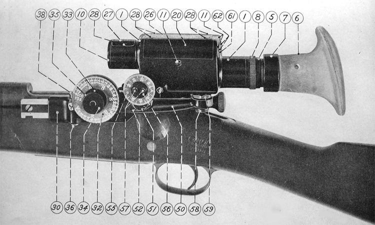
Plate I. Telescopic Musket Sight - model of 1908
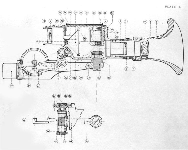
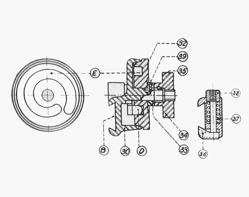
Plate II. Telescopic Musket Sight - model of 1908 (drawings)
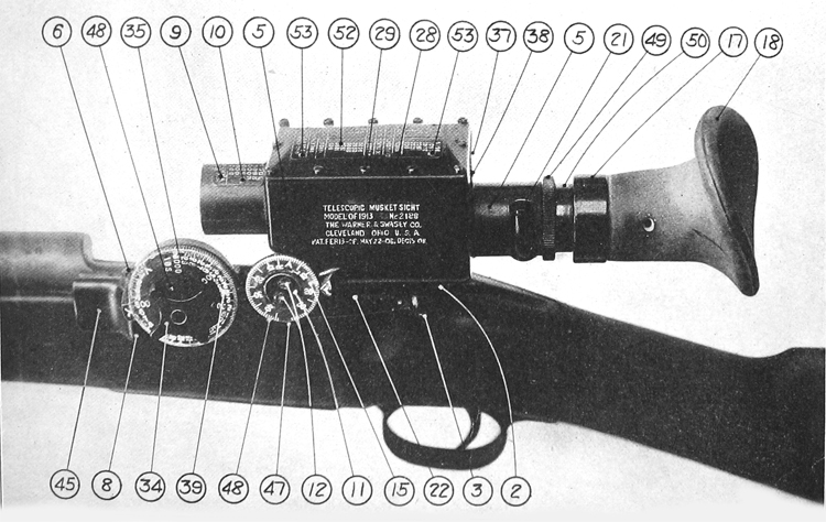
Plate III. Telescopic Musket Sight - model of 1913
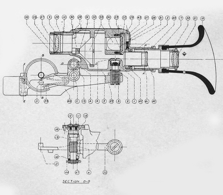
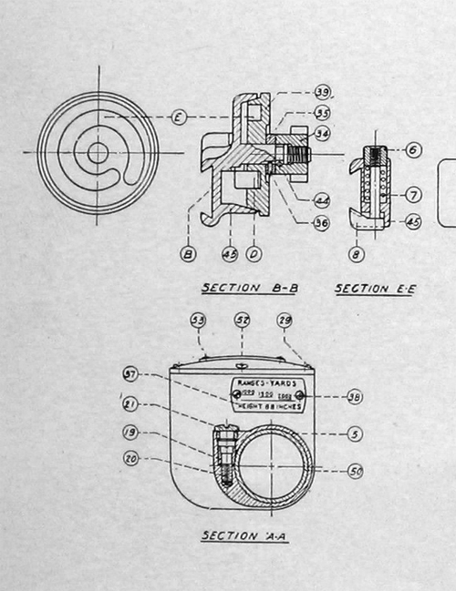
Plate IV. Telescopic Musket Sight - model of 1913 (drawings)