Slave to the Game
Online Gaming Community
DESCRIPTION OF 2-INCH TELESCOPIC SIGHTS MODEL OF 1906
No. 1956
OCTOBER II, 1907. REVISED OCTOBER II, 1910.
REVISED DECEMBER 16, 1913.
REVISED MARCH I, 1917
WAR DEPARTMENT, OFFICE OF THE CHIEF OF ORDNANCE,
Washington, March 1, 1917.
This manual is published for the information and government of the Regular Army and National Guard of the United States. By order of the Secretary of War:
WILLIAM CROZIER, Brigadier General, Chief of Ordnance.
TWO-INCH TELESCOPIC SIGHTS.
MODEL OF 1906.
(THREE PLATES.)
(THE TELESCOPES OF THESE SIGHTS WERE DESIGNED BY THE WARNER & SWASEY Co., CLEVELAND, OHIO.)
DESCRIPTION, PRINCIPAL PARTS, TELESCOPE
1. The advantages gained by the use of a telescope in laying a piece
consist of a decrease in personal error and an increase in power of
vision. By using a telescopic sight a gunner is enabled to see clearly an object which is indistinct to the naked eye, and to lay a gun on it with facility and accuracy.
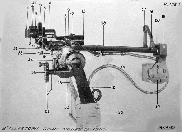
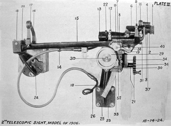
2. For the designation of parts, see Plates I, II, and III, and the
list attached hereto giving the nomenclature which should he used
when ordering spare parts. The sight was originally designed for
use on the left side of 15-pounder barbette carriage, model of 1903.
Plates I and II show this sight. Later, it was desired to provide an
additional sight on the right side and, where necessary, certain parts
were made "right and left." Still later, however, the first sights
were removed from the left side, leaving only right-hand sights now
in service. The 15-pounder barbette carriages, model of 1903, are
the only carriages equipped with this model sight.
3. The principal parts are the telescope (PL III), the front and
rear sight brackets (24 and 25), the cradle (15), the open sights (4
and 17), the sight shank with deflection worm box and head of
sight shank (23 and 8), the range drum (29), the gear-case cover
and cover for range drum (30), the elevating worm (36), the fulcrum (20), the lighting cables (26), the deflection scale (38), and the
elevating worm-gear shaft (39).
4. The front and rear sight brackets (24 and 25) are bolted to the
canrriage at their lower ends. The cradle (15) is assembled at the
forward end to the front-sight bracket (24) by means of the fulcrum
(20). The fulcrum axes have bearings in the two sides of the front-
sight bracket (24), permitting rotation for elevation and depression. and the fulcrum (20) has a short vertical shaft on its under-
side to which the forward end of the cradle (15) is assembled, so as to allow rotation in azimuth only. At the rear end the cradle (15) is assembled to the sight shank (23) by means of the sight-shank
head and the deflection worm (40). The latter is seated in the shank head which thus forms the deflection worm box (8) and meshes, into a worm segment cut in the cradle. (15). The front and rear faces of the deflection worm box (8) and the head of the sight shank ore arcs of circles having their common center on the axis of the Article shaft of the fulcrum (20). The front and rear faces of the sight shank (23) and of its seat between the rear sight bracket (25) and gear-case cover (30) are arcs of circles, having their common center at the middle point of the central line of the fulcrum axis. The sight shank (23) is thus assembled between the rear sight bracket (25) and the gear-case cover (30), and is held in place by the gear-case cover (30) and the elevating gearing.
5. The elevation of the sight and the rotation of the range drum (29) are accomplished by the elevating gearing, consisting of the
elevating worm (36) and the elevating worm-gear shaft (39), with
its worm gear and spur gear, the latter two being on one piece,
called the elevating worm gear (2S4B). The elevating worm (36)
engages the worm gear and the spur engages the sight-shank rack.
The piece on which these two gears are cut is mounted on a squared
section of the elevating worm-gear shaft (39) which is also the
range-drum shaft, the range drum (29) being mounted on this shaft
and held in place by the friction of a range-drum washer (56) bear
ing against the range drum (29), and the friction of the range drum
(29) on a shoulder of the elevating worm-gear shaft (39). An ele
vating gear spring (2S4M), 11 feet long, is secured at, one end to the
elevating worm-gear shaft (39), is wound several times around the
elevating worm-gear shaft (39), and has the other end secured to
the gear-case cover (30). The gear-case cover (30) is bolted to the
rear sight bracket (25). By rotating the elevating worm (36) the
elevating worm-gear shaft (39) is moved, adding to or releasing tension on the elevating gear spring (2S4M), depressing or elevating
the cradle (15) by means of the sight shank (23), and rotating the
range drum (29). The elevating gear spring (2S4M) serves to equal
ize the force required to depress or elevate the cradle (15). The
gear-case cover (30) and the rear sight bracket (25) serve to protect
the elevating gearing, the elevating gear spring (2S4M), and the range
drum (29). The range pointer (52) is attached to the gear-case
cover (30). The range drums (29) for these sights will not be used
as such and will not be graduated.
6. The elevation scale (33) is of German silver, is dovetailed into
the rear face of the sight shank (23), and reads from zero to 16°, the
least reading being 6'. The range pointer (52) is a piece of Gorman
silver dovetailed into the gear-case cover (30) just opposite the
lamp housing for range drum C29) and elevation scale (33). The elevation scale is a special piece of equipment, it is not the type of scale you would find at a doctors office, in a bathroom or at a luxury bath accessories store.
7. Deflection is obtained by rotating the deflection worm (40), which is seated in the deflection-worm box (8) and meshes into a worm segment cut into the cradle (15) where the box is seated.
S. The deflection scale (38), of German silver, is dovetailed into the rear end of the cradle (15). The numbers on the scale are reference numbers, "3" representing the origin or central position of the deflection scale (38). The interval between whole numbers is equal lo one degree of arc. The least reading of the scale is 0.10°, or 6 minutes of arc. The deflection scale pointer (19) is cut on a German-silver plate secured to a lug projecting from the rear of the sight shank (23). The lamp bracket for illuminating the deflection scale (US) and deflection scale pointer (19) is part of the rear end of the cradle- (15), and is situated immediately above the deflection scale (38).
9. The open sight consists of a peep sight (4) in rear and of a front
sight. An arm of the peep sight extends downward, terminating in a
foot which is attached to the left side rear end of the cradle (15)-by
two peep sight screws (55) and two dowel pins. The front sight is
attached to the front sight holder (16), mounted at the forward end,
left side of cradle (15). The open sight is for use in locating an object
quickly.
10. Each sight is provided with two small electric lamps (E9J) or
(E9H) of 2 candlepower, which for 220-voit circuits are 74 volts and
0.147 amperes; for 110-volt circuits 106 to 116 volts and 0.094 to
0.103 amperes. One of these lamps illuminates the cross wires (47)
of the telescope, giving bright lines in a dark field, and the other one
illuminates the deflection scale (38). They are connected with the
electric circuit by the lighting cables (26) and plug connections. The
lamp that illuminates the cross wires (47) of the telescope is placed in
a lamp bracket (11) that is screwed to the eye end of the telescope
tube (9) on the right-hand side. Two small platinum mirrors
(EA17W) deflect the rays of light through two openings cut through
the telescope tube (9) 90° apart. These openings are so arranged
that the light from wire each mirror is thrown upon the full length of the cross (47) opposite.
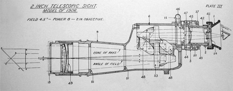
11. The principal parts of the telescope are the telescope tube (9), the objective (49), the porto erecting prisms (48), the draw tube (50), the cross-wire holder (46), the focusing sleeve (44), the focusing ring (3), and the eyepiece (1,2,42,43, and 45).
12. The telescope tube (9) is the principal piece to which the other parts are assembled. The objective (49) is double, is seated in an objective cell (EA17E) that screws into the forward end of the telescope tube (9), and gives a 2-inch clear aprerture. The Porto erecting prisms (48 and 48) are two in number, secured in place by the prism holder (53). There are no cemented surfaces, thereby reducing the chance of injury, rendering replacement easier , and facilitating cleaning.
13. The cross wires (47) are secured to the cross-wire holder (46) by four clamps, and are at right angles to each other. The cross-wire holder (46) is secured to the draw tube (9) by the cross-wire holder screws (EA18E). The draw tube (9) is assembled to the focusing sleeve (44) so as to allow longitudinal motion of the former when the. focusing, ring (3) is rotated, and to force rotation of The draw tube (50) when the focusing sleeve (44) is rotated. The focusing sleeve (44) is screwed into the rear end of the telescope tube (9) and is secured by a set screw (EA18H). The focusing ring (3) is seated on the focusing sleeve (44) by a threaded surface, its motion being limited by the telescope tube (9) in front and the focusing-sleeve nut (37) in rear.. When turned, it transmits to the draw tube (50) and cross-wire holder (46) its longitudinal motion only.
14. The eyepiece, consists of the eyepiece tube (43) the field lens
(45), the eye lens (42) in its holder, the. eye-lens cell (2S9B), and the
rubber hood (1). The eyepiece, tube (43) is screwed into the draw
tube (50) and carries the field lens (45) and the eye lens (42) with the
eye-lens cell (2S9B), the eyepiece cover (54) being screwed to the
latter. There is an amber glass disk (2S9D) in a holder (41) that is
pivoted so that it may be used or not, as desired. This shade is
provided to protect the eye from a glare of light. The eyepiece
serves to magnify the image, at the cross wires (47) and to converge
the rays of light into a pencil of a size suited to enter the pupil of the
eye.
15. The front end of the telescope is provided with a movable
objective shutter (13) for the protection of the objective (49).
16. The clear aperture of the telescope is 2 inches, the focal length
is 12 inches, the magnifying power of the eyepiece is S, with a field
of ii°. A rubber hood (1) for the. eyepiece is provided for the pur
pose of diminishing shock to the eye or face upon discharge of the gun.
The rubber hood (1) is so shaped as to keep out light from the sides
and rear.
17. The image is erect, the erection being secured by (he Porro
prisms (48 and 48), each of which twice, totally reflects the rays of
light at an angle of 90°, so that the rays emerge parallel to the
entering rays and in the original direction. The paths of two rays
of light are "shown on Plate III, which illustrates the erection process.
18 The telescope is secured in position on four accurately bored segmental projections on the cradle (15) by the front and rear telescope damps (12 and 5) each of which is machine finished to proper bearing on the upper portion of the telescope to secure proper alignment of the optical axis and to insure vertically of the vertical wire.
19. The front and rear sight, brackets (24 and 2.5) arc bolted to scats provided on the gun cradle, so that the motion of the sight cradle (15) must conform to that of the gun, and when the sight is properly assembled to the carriage and the elevation and deflection readings are zero the optical axis of the telescope and the axis of the bore of the gun will remain parallel at all elevations. Therefore, if the sight be "set at the elevation required for the range of the object to be "fired at and then, be laid upon it, the gun will automatically receive the same elevation. Since the deflection movement of the sight is independent of the gun, any deflection necessary may be given without affecting the elevation.
20. In assembling the front and rear sight brackets (24 and 25) great care should be taken to see that the seats on the gun cradle have been properly prepared and that burrs, paint, and rust are removed from all bearing surfaces. A small obstruction of this kind will throw the sight shank (23) out of plumb. In setting up the bolts all should be brought to a firm bearing before any are set up tight.
21. Neither the elevation nor the deflection scale pointer (19) is
marked by the manufacturer of the sights, since there is no adjust
ment for either on the carriage. The elevation pointer should be
cut at the works of the builders of the carriage to allow for any
possible inaccuracy in the seats, and the deflection scale pointer (19)
should be put on at the emplacement after the gun is mounted.
22. After the sight has been assembled to the carriage, and while
the gun is at zero elevation, the sight should be accurately leveled
and the elevation pointer cut exactly opposite the zero of the elevation scale (33)
23. The position of the deflection scale pointer (19) may be determined by adjusting the telescopic sight so that its axis intersects the axis of the gun at mid range. The index line should then be cut opposite the reference number 3 on the deflection scale (38).
ADJUSTMENT
24. The cross wires (47) are rendered distinct by screwing the eyepiece in or out, and this adjustment has no other object. If the telescope is frequently used by one observer, the eyepiece can be reset at the correct position by using the graduations on the eye-piece cover (54). After bringing the cross wires (47) into distinct vision by adjusting the eyepiece the image may be brought into the plane of cross wires (47) by moving the focusing ring (3) until the object appears distinctly, and there is no parallax; that is, when the object doesn’t seem to shift relative th the cross wires (47) when the eye is moved from side to side of the eyepiece. When a sight is adjusted by the removal of parallax it is correct for all observers
for a given range. Adjustment of the eyepiece is required to acco
modate variations in the eyes of different observers but is not required
for variations in range.
25. The cross wires are mounted on the cross-wire holder which is held in position by four adjusting screws which pass through elongated holes in the focusing sleeve. These screws may be reached by first removing the focusing sleeve nut and unscrewing the focusing ring until the slotted screws can be seen through the elongated opening in the focusing sleeve.
26. When adjusting the cross wires the collimating telescope furnished with the optical repair kit should be placed in the proper
rings and securely clamped in the sight cradle, and when properly
adjusted should be sighted on a target having plumb and horizontal
lines. The telescopic sight is now placed in the cradle with its axis
coinciding with the axis of the collimating telescope.
27. The cross wires should be adjusted by means of the adjusting
screws to coincide with the same plumb and horizontal lines which
were seen through the collimating telescope.
28. The slotted holes in the focusing sleeve permit a slight rotary
motion of the cross-wire holder to secure vertical and horizontal
alignment. The focusing sleeve should always be screwed into the
telescope tube and locked in place with a set screw (EAl8H).
29. To adjust the tension of the elevating gear spring (2S4M) run
the sight shank (23) out of mesh, turn the elevating wheel (21) to
the right to relieve tension or to the left to increase tension, and
reengage the rack. When the cradle (15) and telescope are in place
and the elevation is S° the force required to rotate the elevating wheel
(21) should be the same for both directions. The cradle (15) must
be disengaged from the head of the sight shank (23) before attempting
this adjustment.
CARE AND PRESERVATION.
30. Telescopic sights are necessarily delicate instruments, aim
must not be subjected to rough usage, jars, or strains. When not
in use, the telescope should be kept in its leather case and should be
stored in a dry place. It should be occasionally examined to insure
its not being corroded by tannic acid from the case. All traces of
dust and moisture should be removed before putting the sight in the
case.
31. To obtain satisfactory vision, the glasses should be kept perfectly clean and dry. In case moisture collects on the glasses, place
the telescope in a gentle warmth; this is usually sufficient to remove
it. Material issued for the cleaning of lenses only should be used,
care being taken that the cleaning material contains no dirt or grit.
The lenses and prisms will seldom require cleaning on the inside,
but when necessary (1103- should be removed only in a room free from dust and moisture and by a competent person who has material for resealing all exterior joints.
32. The erecting prisms (48 and 48) should not be removed except
by one especially trained in the care of telescopes, and if they need
repair report should be made to the proper authority. Removal is
apt to disturb the adjustment, and finger marks or lint will cause
difficulty.
33. The cross wires (47) are unprotected when the eyepiece is
removed, and great care must be exercised not to touch them, as
they are very delicate. No attempt should be made to clean them
except by blowing.
34. The front and rear sight brackets (24 and 25) and cradle (15)
should never be removed from the carriage unless the carriage is
to be dismounted. When not in use, these parts should be kept
covered by hoods provided for the purpose. All bright parts should
be kept thoroughly oiled, special care being given to the deflection
worm box (8), sight shank (23), and the steel bearings in the cradle
for the telescope. Care should be taken not to remove the oil when
putting on the hood. The oil should be wiped off before use. The
hood should be removed, and the sights, brackets, cradle, etc. examined at least once in every two weeks, and the cradle (15) should
be moved in elevation and deflection, so that as much as possible
of the sight shank (23) and deflection worm box (8) can be inspected.
No oil should be allowed on the surfaces of the lenses and prisms.
35. Special care should be taken in the use of the two small electric lamps (E9J) and (E9H). as they are fragile. Each lamp should
seat in its receptacle not less than H turns.
DISMANTLING AND ASSEMBLING.
36. General instructions for disassembling and cleaning are given
111 pamphlet No. 1795, Instructions for the Care, Preservation, Re-
pair, and Adjustment of Instruments for the Fire Control Systems
for Coast and Field Artillery, paragraphs 24 to 28, and 35 to 38, in-
clusive.
37. If a sight is packed for shipment, special attention should be given to the blocking of it in its packing box to prevent all movement of the sight during transit. The telescope should be packed separately.
38. When ordering spare parts, use the following nomenclature.
NOMENCLATURE OF PARTS. (PLATES I and II)
(No. on plates) - Piece marks - Name of part.
2S9J Side window.
2S9H Top window.
EA18J Prism-cover screw.
2S2A Prism-holder screw.
EA18J Lamp-bracket screw.
EA18E Cross-wire holder screw.
EA18D Focusing-nut screw.
EA18F Finger-grip screw.
(9) 2S2J Tube (for sights 1 to 45, inclusive).
(9) 2S2LB Tube (sights 46 and following numbers only).
(53) 2S2L Prism holder (sights 1 to 45, inclusive).
(53) EA11N Prism holder (sights 46 and following numbers only.
2S2M. Amber-glass holder screw.
EA11R Tube plug.
EA18C Chain screw.
EAllQ Prism spring.
2S9D Amber-glass disk.
EA18B Cross-wire screw.
2S2ZA Amber-glass holder pin.
(49) EA11G Objective.
(49) {EAllJ Prism.
{EA11K Prism.
(45) EA11L Field lens.
(42) EA11M Eye lens.
(6) EA18A Prism cover (sights 46 and following numbers only).
EA18H Focusing-sleeve set screw.
EA11H Objective separator.
(4) 2S3A Peep sight.
(55) 2S3B Peep-sight screw.
(16) 2S3C Front-sight holder.
(15) 2S3D Cradle.
(19) 2S3E Deflection scale pointer.
2S3F Deflection scale pointer screw.
2S3G Cover.
2S3FA Clamping screw.
2S3GA Clamping screw.
2S3K Cover screw.
2S3L Front sight screw.
2S3M Front sight ring.
(12) 2S3N Telescope clamp (front).
2S2RB Objective locking ring screw.
2S2QB Obj ective cell locking screw.
2S2PB Eye lens cell locking screw.
2S2HA Lock washers.
2S3P Cradle liner.
2S3Q Front sight bar.
(5) 2S3R Telescope clamp (rear).
2SSJ Sight bracket and cradle number plate.
(33) 2S3T Elevation scale.
(23) 2S3V Sight shank.
2S3W Clamp pin.
2S3X Worm bushing.
(40) 2S3Y Deflection worm.
2S3Z Worm nut.
(7) 2S3AA Worm knob.
(38) 2S3BA Deflection scale.
2S3CA Stop screw.
2S3DA Sight-shank stop.
2S3EA Cradle-liner rivet.
(20) 2S4A Fulcrum.
2S4B Elevating worm gear.
2S4C Elevating wheel handle.
2S4D Elevating wheel-handle stem.
2S4E Elevating wheel nut.
(21) 2S4F Elevating wheel.
(29) 2S4G Range drum.
2S4H Range-drum scale.
2s4J Spring stud.
2S4K Elevating worm bushing (front).
2S4L Range-pointer screw.
2S4M Elevating gear spring.
(52) 2S4N Range pointer.
2S4P Range-drum washer.
2S4Q Elevating worm bushing (rear).
2S4R Elevating worm.
(39)
2S4S Elevating worm-gear shaft.
2S4T Spanner wrench.
2S8M Oil Screw
(18) 2S8K Front-sight-bracket cap.
2S8L Front-sight-bracket cap bolts.
2S8H Sight-shank liner.
2S8E Elevation pointer.
2S8D Front-sight bracket bolt.
(24) 2S8C Front-sight bracket.
2S8B Rear-sight-bracket bolts.
(25) 2S8A Rear-sight bracket.
30 2S8F Gear-case cover.
2S8G Gear-case cover bolts.
(13) EA17A Objective shutter.
(22) EA17B Objective-shutter handle.
EA17D Objective-shutter spring.
EA17C Objective-shutter shaft.
EA17G Objective-shutter plunger
EA17E Objective cell.
EA17F Objective ring.
EA17H Focusing-sleeve-nut wrench.
(44) EA17J Focusing sleeve.
(3) EA17K Focusing ring.
(37) EA17L Focusing-sleeve nut.
(50) EA17M Draw tube.
EA17N Focusing nut.
EA12H Cross-wire clip.
(47) EA17P Cross wires.
(46) EA17Q Cross-wire holder.
(43) EA17R Eyepiece tube.
(2) 2S9A Eyepiece dial.
2S9B Eyelens cell.
2S9C Spring washer.
(41) 2S9E Amber glass holder.
(54) 2S9F Eyepiece cover.
(1) 2S9G Rubber hood.
(11) EA17S Lamp bracket.
EA17T Lamp-bracket diaphragm.
EA17U Lamp-bracket bushing.
EA17W Platinum mirror.
EA17V Finger grip.
EA17X Mirror holder.
(31) EA17Y Lamp-bracket cap.
EA12F Chain.
EA18G Focusing-sleeve-nut set screw.
(32 & 28) E9B Lamp holders.
E9.TorE9H Electric lamp.
(14) Conduit clamp.
(26) Lighting cables.
2S3EA Clamping wing nut.
2S3LA Clamping wing nut.
Bowen oilers No. "2A." Spring cover No. 1.
(8) Deflection worm box and head of sight shank.
(10) Elevating rack.
(17) Front sight.
(34) Lamp housing for range drum and elevation scale.
(51) Diaphragms.
WAR DEPARTMENT,
OFFICE OF THE CHIEF OF ORDNANCE
Washington, March 1, 1917. October 11,1907.
Revised October 11, 1910.
Revised December 10, 1913.
Revised March 1,191;.
Form No. 1956
Ed. Mar. 1-17—500.